Samsung NS100SSXEA Скачать руководство пользователя страница 79

5-1

Samsung Electronics

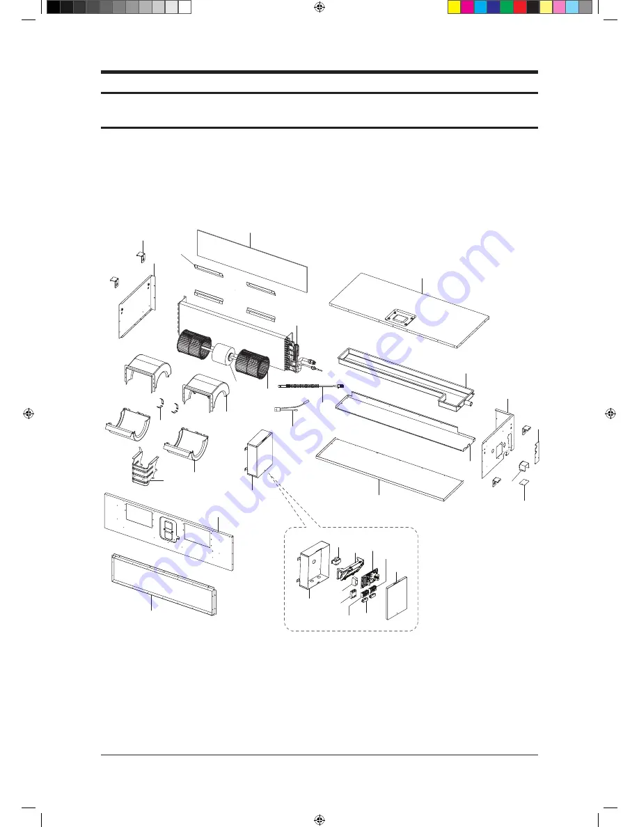
5. Exploded Views and Parts List

5-1 Indoor Unit

13

19

2

18

5

3

9

6

15

17

14

1

15-1

15-3

15-2

15-7

15-6

15-5

15-8

23

23

20

22

21

24

4

8

12

11

7

15-4

16

10

26

  NS090SDXEA

NS090SDXEA_E_SM_33623A(1)_2.indd   1

2011-04-08   �� 11:02:08

Содержание NS100SSXEA

Страница 1: ...XEB RC125DHXGA RC140DHXEB RC140DHXGA INDOOR UNIT OUTDOOR UNIT 1 Precautions 2 Product Specifications 3 Disassembly and Reassembly 4 Troubleshooting 5 ExplodedViews and Parts List 6 PCB Diagram 7 Wirin...

Страница 2: ...k Method 4 3 4 3 Setting Option Setup Method 4 4 4 3 1 Type A Setting Option 4 4 4 3 2 Type B Setting Option Setup Method 4 6 4 3 3 Option code for each model 4 16 4 4 Items to be checked first 4 17 4...

Страница 3: ...35 4 7 Main Part Inspection Method 4 36 15 Exploded Views and Parts List 5 1 5 1 Indoor Unit 5 1 5 2 Outdoor Unit 5 7 5 3 Ass y Control Out 5 11 16 PCB Diagram 6 1 6 1 PCB Diagram 6 1 6 1 1 Indoor Uni...

Страница 4: ...ircuit Fasten the valve caps of service valves and charging valves of outdoor unit as much as possible using adjustable wrenches Check the status of the components assembly after repair service The st...

Страница 5: ...rate the batteries from the remote controllers and store them separately when the product is not used for long time Otherwise leakage from the dry cell may cause problems with the remote controller 1...

Страница 6: ...makes a room cool with highly energy saving and arises the efficiency of air conditioner Long Piping Length Height It can give the benefit to the installers and aries the reliability of the air condit...

Страница 7: ...70 2780 3720 Operation current Cooling STD A 13 0 14 0 16 0 Heating STD A 12 5 13 0 15 0 Noise Cooling Heating Indoor unit In case of strongest air blow A 48 49 49 50 49 50 Outdoor unit In case of str...

Страница 8: ...TD W 3100 3100 Operation current Cooling STD A 13 8 5 0 Heating STD A 13 5 5 0 Noise Cooling Heating Indoor unit In case of strongest air blow dB 49 50 49 50 Outdoor unit In case of strongest air blow...

Страница 9: ...consumption Cooling STD W 3890 3890 Heating STD W 3880 3880 Operation current Cooling STD A 17 8 6 0 Heating STD A 17 8 6 0 Noise Cooling Heating Indoor unit In case of strongest air blow dB 50 51 50...

Страница 10: ...50 4650 Heating STD W 4430 4430 Operation current Cooling STD A 21 3 7 2 Heating STD A 20 3 6 9 Noise Cooling Heating Indoor unit In case of strongest air blow dB 50 51 50 51 Outdoor unit In case of s...

Страница 11: ...DB98 28943A 5 Insulation DB62 03439J 1 DB62 03439H 1 Insulation Drain In DB62 03440H 1 Insulation Install Inlet DB72 00143E 1 DB72 00143G 1 Ass y Holder Drain Pipe DB90 02064A 1 Ass y Drain Hose Joint...

Страница 12: ...crew 2 User s manual DB98 05160A 1 Installation manual DB98 05186A 1 Wire kit DB39 00223A MRW 10A 1 Receiver display unit DB93 01066A MRK A00 1 Standard type M4x12 Tapped Screw 7 Cable tie 2 User s ma...

Страница 13: ...RH 401 1 Optional Batteries for remote controller specification AAA type DB47 90024A 2 Remote controller holder DB61 00204A 1 STS 2S 2x10 Tapped Screw 6002 000581 2 User s manual DB98 05156A 1 Install...

Страница 14: ...rk Wireless remote controller DB93 04858C MR BH01 1 Optional Batteries for remote controller specification AAA type DB47 90024A 2 Remote controller holder DB61 03147A 1 STS 2S 2x10 Tapped Screw 6002 0...

Страница 15: ...oller DB97 14333C MWR WH02 1 Optional Cable tie DB65 10088B 2 Cable clamp DB65 10074E 5 M4 16 Tapped Screw 6002 000474 7 Indoor unit power drawing cable DB39 00221A 1 Communication cable of thewired r...

Страница 16: ...m Descriptions Code No Q TY Remark Centralized controller DB93 03425C MCM A202 1 Optional Cable tie DB65 10088B 2 Cable clamp DB65 10074E 5 M4x16 Tapped Screw 6002 000474 7 User s manual DB98 12721A 1...

Страница 17: ...ble tie DB65 10088B 2 Cable clamp DB65 10074E 6 M4x16 Tapped Screw 6002 000474 7 User s manual DB98 27317A 1 Installation manual DB98 27315A 1 Transmitter Item Descriptions Code No Q TY Remark Transmi...

Страница 18: ...Descriptions Code No Q TY Remark DMS DB93 03709B MIM D00 1 Optional Cable tie DB65 10088B 2 Cable clamp DB65 10074D 2 M4x16 Tapped Screw 6002 000474 5 Bottom hook DB73 00320A 4 User s manual DB98 273...

Страница 19: ...3 1 Samsung Electronics Item Remarks SCREW DRIVER Adjustable Wrench 8mm 10mm 13mm Necessary Tools 3 Disassembly and Reassembly NS090SDXEA_E_SM_33623A 1 _1 indd 1 2011 04 08 10 54 36...

Страница 20: ...es indicating screws detach Ass y Cabi Bottom Blower Use Screw Driver 2 Detach from Ass y Control In the capacitor connection wire between the Motor Fan and housing connector 3 After disassembling 2 p...

Страница 21: ...sassembling 2 places indicating screws detach Fan Motor and Blower from the set 2 Control In 1 After disassembling 1 Indicating screw detach the Cover control Use Screw Driver 2 Detach the Motor Fan a...

Страница 22: ...ark 3 Disassemble 4 indicating screws and detach Control In from the set 3 Drain Pan Work is possible when Disassembling the Ass y Cabi Bottom Blower 1 Disassemble 7 indicating screws and detach Ass y...

Страница 23: ...4 indicating screws and detach the Drain Pan Use Screw Driver 2 screws each at left and right side 4 Evap Work is possible when Disassembling the Ass y Drain Pan 1 Disassemble 5 indicating screws to...

Страница 24: ...rocedure Remark 2 Disassemble Sensor on the Evap 3 Disassemble 4 indicating screws which are in the near of Hanger Plate to detach the Evap Use Screw Driver 2screwseachatleftandrightside It needs 2 pe...

Страница 25: ...ting screw in the Cabinet Front RH Use Screw Driver 2 Cabi Top 1 Unscrew and remove 9 screws on each side of the Cabinet Top Use Screw Driver 3 Cabi Install Front 1 Unscrew and remove 1 screw in the C...

Страница 26: ...1 Pull the sensor from Guard Cond 2 Unscrew and remove 4 screws in the Guard Cond Use Screw Driver 5 Cabi Back RH 1 Pull the sensor from Cabi Back RH 2 Unscrew and remove 4 screws on each side of the...

Страница 27: ...ts Procedure Remark 6 Cabi Install Back 1 Unscrew and remove 1 screw in the Cabinet Install Back Use Screw Driver 7 Cabi Front LF 1 Unscrew and remove 10 screws in the Cabinet Front LF Use Screw Drive...

Страница 28: ...ctronics 3 10 Disassembly and Reassembly No Parts Procedure Remark 8 Fan 1 Turn 2 mounting nuts as shown in the picture and remove it Use Adjustable Wrench NS090SDXEA_E_SM_33623A 1 _1 indd 10 2011 04...

Страница 29: ...eparate the Fan Propeller 2 Unscrew and remove the 8 Motor mounting screws Use Screw Driver 3 Disconnect the Motor wire From Ass y Control Out 10 Bracket Motor 1 Unscrew and remove 2 mounting screws i...

Страница 30: ...bly No Parts Procedure Remark 11 Control Out 1 Disconnect 4 Connecters From Ass y Control Out 2 Unscrew and remove 1 mounting screw in Control Out Use Screw Driver 3 Separate Ass y Control Out NS090SD...

Страница 31: ...ng screws in muffler 3 Unscrew and remove 2 mounting screws in Service Valve Use Screw Driver 4 Separate the pipe from the Entrance Exit using a welder When removing the compressor Heat Exchanger and...

Страница 32: ...w and remove 2 mounting screws in Service Valve Use Screw Driver 2 Separate the pipe from the Entrance Exit using a welder 14 Compressor 1 Unscrew and remove 1 mounting nut in Cover Terminal Use Adjus...

Страница 33: ...shown in the picture unscrew and remove 3 mounting screws from the bottom Use Adjustable Wrench 15 Cond Out 1 Unscrew and remove 3 screws on each side of the Assy Cond Out Use Screw Driver 2 Separate...

Страница 34: ...y 1 Unscrew and remove 2 mounting screw in the Cabinet Front RH Use Screw Driver 2 Cabi Top 1 Unscrew and remove 9 screws on each side of the Cabinet Top Use Screw Driver 3 Cabi Install Front 1 Unscre...

Страница 35: ...1 Pull the sensor from Guard Cond 2 Unscrew and remove 4 screws in the Guard Cond Use Screw Driver 5 Cabi Back RH 1 Pull the sensor from Cabi Back RH 2 Unscrew and remove 4 screws on each side of the...

Страница 36: ...ts Procedure Remark 6 Cabi Install Back 1 Unscrew and remove 1 screw in the Cabinet Install Back Use Screw Driver 7 Cabi Front LF 1 Unscrew and remove 10 screws in the Cabinet Front LF Use Screw Drive...

Страница 37: ...g Electronics Disassembly and Reassembly No Parts Procedure Remark 8 Fan 1 Turn 2 mounting nuts as shown in the picture and remove it Use Adjustable Wrench NS090SDXEA_E_SM_33623A 1 _1 indd 19 2011 04...

Страница 38: ...eparate the Fan Propeller 2 Unscrew and remove the 8 Motor mounting screws Use Screw Driver 3 Disconnect the Motor wire From Ass y Control Out 10 Bracket Motor 1 Unscrew and remove 2 mounting screws i...

Страница 39: ...bly No Parts Procedure Remark 11 Control Out 1 Disconnect 4 Connecters From Ass y Control Out 2 Unscrew and remove 1 mounting screw in Control Out Use Screw Driver 3 Separate Ass y Control Out NS090SD...

Страница 40: ...rate the pipe from the Entrance Exit using a welder When removing the compressor Heat Exchanger and Pipe purge the Coolant inside the Compressor completely and remove the pipe with a welding flame 13...

Страница 41: ...Compressor 1 Unscrew and remove 1 mounting nut in Cover Terminal Use Adjustable Wrench 2 Separate the Compressor Felt Sound 3 As shown in the picture unscrew and remove 3 mounting screws from the bott...

Страница 42: ...ronics 3 24 Disassembly and Reassembly No Parts Procedure Remark 15 Cond Out 1 Unscrew and remove 3 screws on each side of the Assy Cond Out Use Screw Driver NS090SDXEA_E_SM_33623A 1 _1 indd 24 2011 0...

Страница 43: ...ror of the condensor temperature sensor Error of the discharge temperature sensorPower reset X X X 1 No communication for 2 minutes between indoor units Communication error for more than 2 minutes 2 I...

Страница 44: ...Short Error Power cable miss connection error Indoor Float Switch 2nd Detection Self Diagnosys Error Outdoor unit indoor unit communication wire miss connection Connected to Power terminal Outdoor un...

Страница 45: ...nsor error 9 Discharge over temperature 10 Discharge temperature sensor error 11 Current sensor error 12 Compressor Limit error 13 Coil temperature sensor error 14 1min Time out Communication 15 Fan e...

Страница 46: ...reads or repeatedly Push the button to set the display panel to Every time you push the button the display panel reads repeatedly Push the button to set the display panel to Every time you push the bu...

Страница 47: ...rt to and check the display part The display part shows Press the Mode Selection key to set the display part to and check the display part The display part shows Step 4 Pressing the ON OFF button When...

Страница 48: ...r is indicated as shown in the right then go to the step 2 Step 2 Method If the first digit of remote controller shows 0 go to the step 3 If it shows 1 press the Mode button one time to change it into...

Страница 49: ...sult If 1 is displayed go to the step 5 Step 5 Method Input the third digit of option code by pressing the High Fan button example 021E311422852A311439421F Result If E is displayed go to the step 6 St...

Страница 50: ...ter completion up to step 7 pressing Mode button 1 7 steps are saved internally If the first number is 1 at the time it is correct So go to step 9 If wanting to see the screen of 2 7 steps press the m...

Страница 51: ...21F Result If 2 is displayed go to the step 11 Step 11 Method Input the tenth digit by pressing the High Fan button example 021E311422852A311439421F Result If 2 is displayed go to the step 12 Step 12...

Страница 52: ...mer and Fan indicator is flickering the wrong option code is input Put off the power of indoor unit and turn it on again and then input the option code again If the same error occurs it is the EEPROM...

Страница 53: ...21F Result If A is displayed go to the step 16 Step 16 Method Input the 15th digit by pressing the Low Temp button example 021E311422852A311439421F Result If 3 is displayed go to the step 17 Step 17 M...

Страница 54: ...ut the 18th digit by pressing the Cancel button example 021E311422852A311439421F Result If 4 is displayed go to the step 20 Step 20 Method After completion up to step 20 pressing Mode button Previous...

Страница 55: ...21F Result If 9 is displayed go to the step 22 Step 22 Method Input the 21th digit by pressing the Low Temp button example 021E311422852A311439421F Result If 4 is displayed go to the step 23 Step 23 M...

Страница 56: ...ference to the right side Error If the On Off Timer and Fan indicator is flickering the wrong option code is input Put off the power of indoor unit and turn it on again and then input the option code...

Страница 57: ...from the current ones Check the option code and press the button again if correct Option code will be input Check the option code correctly At the time if the same error continues to occur the option...

Страница 58: ...4 4 1 5 6 2 9 3 NS125SDXEA 0 1 1 0 4 4 1 5 7 0 F 8 NS140SDXEA 0 1 1 0 4 4 1 6 7 2 0 8 Model SEG13 SEG14 SEG15 SEG16 SEG17 SEG18 SEG19 SEG20 SEG21 SEG22 SEG23 SEG24 Remocon display NS100SSXEA 2 7 5 A...

Страница 59: ...essor is reoperated The same phenomenon occurs when a power is on As a phenomenon that the compressor is reoperated after a delay of 3 minutes the indoor fan is adjusted automatically with reference t...

Страница 60: ...unit terminal block voltage on V1 V2 12Vdc nominal Press the On Off button on the wired remote controller to operate the air conditioner Check DC power voltage of remote controller V1 V2 Check DIP SW...

Страница 61: ...s the FUSE on INVERTER PCB blown Is R100 on INVERTER PCB open 200ohm moninal Check INVERTER PCB Are wire and socket connected correctly CN05 06 07 TAB terminal EMI PCB CN20 INVERTER PCB Check and corr...

Страница 62: ...f CN40 and 41over 250V Is the Pin voltage 5 3 of CN40 and 41 15V Is the Pin voltage 5 3 of CN40 and 41within 1 6V during the operation Is the Fan in rotation during TEST operation in cooling mode Is t...

Страница 63: ...or unit cover Fan front obstruction etc 7 Is there no ventilation obstruction at the surrounding of indoor unit Overload condition in heating mode 2 Troubleshooting procedure Yes Yes Yes Yes Yes Is th...

Страница 64: ...ctly Is the 4 WAY valve connectorconnected correctly Dose thevoltage of AC220V apply to the connector of 4 WAY valve coil during the operation Change the setting temperature of remote control Check In...

Страница 65: ...ctedcorrectly Is much frostin the heat exchanger Is much frostin the heat exchanger Connect the connector Exchangethe out PCB The over shortage of refrigerant Insufficient Capacity Load estimation err...

Страница 66: ...r connectedcorrectly in accordance with a color Is the temperature sensor connectedcorrectly without separation Does the both terminal of sensorsatisfy the resistance value in accordance with temperat...

Страница 67: ...connectedcorrectly in accordance with a color Is the temperature sensor connectedcorrectly without separation Does the both terminal of sensorsatisfy the resistance value in accordance with temperatu...

Страница 68: ...connectedcorrectly in accordance with a color Is the temperature sensor connectedcorrectly without separation Does the both terminal of sensorsatisfy the resistance value in accordance with temperatur...

Страница 69: ...ccordance with temperature 4 Is the resistance value of sensor connection pull_up correct 2 Troubleshooting procedure Yes Yes Yes Isn t the Fan locked Is the connector connected correctly Is the color...

Страница 70: ...on of R S T power wire normal 2 Are Relay RY21 and R200 on the INVERTER PCB mounted normally 2 Troubleshooting procedure Yes Are connection of the wire from INVERTER PBA to EMI PBA normal Exchange INV...

Страница 71: ...od Is the installation of indoor unit good Are the service valves full opened Does the compressor wire connected to the compressor normally Is insuration resistance between each compressor terminal an...

Страница 72: ...Restart after power off Is the communication erroroccurred again Isn t the power cable andcommunication cable wiring error Is the connection of communication cable normal Is insuration resistance betw...

Страница 73: ...estart after power off Is the restart error occurred again Is the interphase resistance value of compressor u v v w w u normal Is the compressor body and interphase resistance insulated Is the connect...

Страница 74: ...t after power off Is the lock error occurred again Is the interphase resistance value ofcompressor u v v w w u normal Is the compressor body and interphase resistance insulated Is the connection cable...

Страница 75: ...on of reactor terminal good Are the FUSEs on EMI PCB blown Push the center bar of M C and mesure the resis tance of each contact Is each contact resistance normal less than 0 1ohm Does the error reapp...

Страница 76: ...lying circuit Display PCB part LED lamps Switch Remocon module INDOOR EMI PCB part Line filter Noise Capacitor and Varistor 3 The PCB is composed of the 3 part in the outdoor unit EMI PCB part Line fi...

Страница 77: ...ing once a second 3 Is LEDs displaying error code pattern MAIN PCB power trouble Bad communication between indoor and outdoor unit Error detection 5 Check LED display on INVERTER PCB 1 Is RED LED ON 2...

Страница 78: ...th a multimeter Normal At the normal temperature 37k 8 3k 7 C 30 C see 12 2 6 and 12 2 8 Abnormal 0 Open or Short Outdoor Unit Discharge Temperature Sensorr Measure terminal resistance with a multimet...

Страница 79: ...5 Exploded Views and Parts List 5 1 Indoor Unit 13 19 2 18 5 3 9 6 15 17 14 1 15 1 15 3 15 2 15 7 15 6 15 5 15 8 23 23 20 22 21 24 4 8 12 11 7 15 4 16 10 26 NS090SDXEA NS090SDXEA_E_SM_33623A 1 _2 ind...

Страница 80: ...ASS Y 1 SNA 15 1 DB90 01992A ASS Y CASE CONTROL ASS Y 1 SA 15 2 DB00 00000A CASE PCB ABS V0 T2 5 1 SA 15 3 DB26 00080A TRANS POWER AC 230V 50HZ DC 17V DC 0 6A VDE ICE 1 SNA 15 4 3502 001035 SSR DC 12V...

Страница 81: ...arts List 1 5 6 15 16 9 8 10 4 14 13 7 18 21 2 3 17 12 11 17 8 17 4 17 10 17 6 17 3 17 9 17 7 17 1 17 2 18 1 18 8 18 4 18 7 18 2 18 5 17 5 18 6 19 18 3 20 22 NS140SDXEA NS100SDXEA S125SDXEA NS090SDXEA...

Страница 82: ...0 02028A ASS Y CABI FRONT ASS Y SGCC M T1 5 1 SNA 17 2 DB90 02013A ASS Y BRACKET OUTLET PART ASS Y SGCC M T1 0 1 SA 17 3 DB61 02372A BASE MOTOR ASS Y SGCC M T2 5 1 SNA 17 4 DB61 02375A BRACKET MOTOR A...

Страница 83: ...SXEX NS100SSXEA NS100SSXEX 10 11 15 3 14 7 14 8 14 4 15 2 15 6 15 1 15 5 15 4 15 7 15 8 1 13 12 9 4 7 11 15 10 8 2 14 5 6 2 3 14 6 14 1 14 2 14 3 14 5 16 17 Exploded Views and Parts List NS090SDXEA_E_...

Страница 84: ...T SGCC M T0 8 1 1 1 SA 12 DB63 01299D FILTER PR EASS Y T4 5 178 985 NATURE 1 1 1 SA 13 DB96 07024C ASS Y EVAP UNIT DH094EAMC 220 240V 50HZ 9 4KW 1 SA DB96 07024G ASS Y EVAP UNIT DH094EAMC 220 240V 50H...

Страница 85: ...ctronics RC090DHXEA RC090SHXEA RC100SHXEA RC100DHXEA RC100DHXGA 7 7 1 14 15 13 22 21 16 9 8 1 11 5 18 23 23 1 23 2 4 3 19 20 17 6 2 23 3 10 12 5 2 Outdoor Unit NS090SDXEA_E_SM_33623A 1 _2 indd 7 2011...

Страница 86: ...SA 14 DB60 00405A FASTENER WASHER M8 1 1 SNA 15 DB67 01061A FAN PROPELLER PP MICA GF 520PI 1 1 SA 16 DB90 05918A ASS Y BRACKET MOTOR ASS Y 1 1 SA 17 DB60 30028A SCREW HEX HWH WP M8 ZPC WHT SWRCH18A 3...

Страница 87: ...tronics Exploded Views and Parts List 14 18 19 23 5 11 1 8 23 1 23 2 23 3 17 20 3 10 12 4 2 6 15 13 16 21 22 9 7 7 1 RC125DHXEB RC125DHXGA RC140DHXEB RC140DHXGA NS090SDXEA_E_SM_33623A 1 _2 indd 9 2011...

Страница 88: ...5 04522B ASS Y THERMISTOR OUT MANU ASS Y 1 1 SA 13 DB31 00579A MOTOR FAN DAO335130ZRC CLASS E 2 2 SA 14 DB60 00405A FASTENER WASHER M8 2 2 SNA 15 DB67 01057A FAN PROPELLER PP MICA GF 480PI 2 2 SA 16 D...

Страница 89: ...sung Electronics 3 4 5 2 6 12 11 1 7 8 13 10 9 12 2 8 5 8 4 8 3 8 2 8 1 12 4 12 1 12 3 5 3 ASS Y CONTROL OUT RC125DHXEB RC125DHXGA RC140DHXEB RC140DHXGA NS090SDXEA_E_SM_33623A 1 _2 indd 11 2011 04 08...

Страница 90: ...B SUB EMI Inverter Platform 4 5 EMI 1 1 SA DB93 11111A ASS Y PCB SUB EMI Inverter Platform 6 EMI 3 1 SA 9 DB91 00306A ASS Y SCREW MACHINE M3 L16 2 2 SA 10 DB91 00307A ASS Y SCREW MACHINE M4 L16 2 2 SA...

Страница 91: ...s S W Temperature Sensor SMW250 02 WHT Indoor Option S W Heater Discharge SMW250 02 YEL Indoor Fan TAP YW396 09AV WHT Temperature Sensor SMW250 02 YEL Ventilator YW396 03AV BLK Wired Remote Controller...

Страница 92: ...r SMW250 02 YEL Ventilator YW396 03AV BLK Wired Remote Controller Power YW396 02 WHT Drain Pump YW396 03AV YEL External Control S W Part SMW250 02 RED Hot Coil YW396 03AV RED EEV SMW250 05 BLU SMW250...

Страница 93: ...6 3 Samsung Electronics PCB Diagram 6 1 2 Outdoor Unit PCB Main PCB 1 5 6 2 3 4 15 7 16 9 11 13 8 10 12 14 NS090SDXEA_E_SM_33623A 1 _2 indd 3 2011 04 08 11 04 44...

Страница 94: ...gnal 5 DC 12V 1 TXD 2 RXD 3 GND 4 DC 5V 5 DC 12V 6 INV SMPS signal 1 Temp signal 2 GND 1 High Pressure temp signal 3 GND 4 DC 5V 1 DC 12V 2 GND 1 COM1 2 COM2 1 DC 12V 2 GND 3 DC 5V 4 COM1 5 COM2 CN11...

Страница 95: ...RXD_ATARO 2 TXD_ATARO 3 8 N C 4 7 DATA signal 9 GND 10 DC 5V For S W engineer debugging 1 DC 360V 2 N C 3 GND 4 DC 15V 5 FAN RPM 6 FAN RPM feedback 1 DC 360V 2 N C 3 GND 4 DC 15V 5 FAN RPM 6 FAN RPM f...

Страница 96: ...RO 3 8 N C 4 7 DATA signal 9 GND 10 DC 5V For S W engineer debugging 1 DC 360V 2 N C 3 GND 4 DC 15V 5 FAN RPM 6 FAN RPM feedback 1 DC 360V 2 N C 3 GND 4 DC 15V 5 FAN RPM 6 FAN RPM feedback 1 COMP U ph...

Страница 97: ...ectronics Outdoor Unit PCB cont EMI PCB 1Phase RC XE L1 BRN N1 SKY BLU 1 3 AC 220 240V L1 AC POWER L phase N1 AC POWER N phase CN01 AC POWER 3 1 2 PCB Diagram NS090SDXEA_E_SM_33623A 1 _2 indd 7 2011 0...

Страница 98: ...8 Outdoor Unit PCB cont EMI PCB 3Phase RC XGA R AC 380 400V WHT S AC 380 400V BRN T AC 380 400V BLK 1 3 AC 220 240V RST AC POWER 3phase CN100 AC POWER 2 1 PCB Diagram NS090SDXEA_E_SM_33623A 1 _2 indd...

Страница 99: ...7 1 Samsung Electronics 7 Wiring Diagram 7 1 Indoor Unit This Document can not be used without Samsung s authorization NS090SDXEA_E_SM_33623A 1 _2 indd 1 2011 04 08 11 05 18...

Страница 100: ...Samsung Electronics 7 2 Wiring Diagram 7 2 Outdoor Unit Outdoor Unit RC XE This Document can not be used without Samsung s authorization NS090SDXEA_E_SM_33623A 1 _2 indd 2 2011 04 08 11 05 20...

Страница 101: ...7 3 Samsung Electronics Outdoor Unit RC XGA Outdoor Unit cont This Document can not be used without Samsung s authorization NS090SDXEA_E_SM_33623A 1 _2 indd 3 2011 04 08 11 05 23...

Страница 102: ...MEMO Samsung Electronics 7 4 NS090SDXEA_E_SM_33623A 1 _2 indd 4 2011 04 08 11 05 23...

Страница 103: ...8 Schematic Diagram 8 1 Indoor Unit 8 1 1 MAIN PCB Samsung Electronics 8 1 This Document can not be used without Samsung s authorization NS090SDXEA_E_SM_33623A 1 _2 indd 1 2 2011 04 08 11 09 12...

Страница 104: ...Document can not be used without Samsung s authorization Schematic Diagram MAIN PCB Samsung Electronics Schematic Diagram 8 7 8 1 2 Outdoor Unit PCB NS090SDXEA_E_SM_33623A 1 _2 indd 3 4 2011 04 08 11...

Страница 105: ...an not be used without Samsung s authorization Schematic Diagram outdoor unit pcb cont Inverter PCB 1Phase I RC HXE Samsung Electronics Schematic Diagram 8 8 NS090SDXEA_E_SM_33623A 1 _2 indd 5 6 2011...

Страница 106: ...nt can not be used without Samsung s authorization Schematic Diagram outdoor unit pcb cont EMI PCB 1Phase RC XE Samsung Electronics Schematic Diagram 8 10 NS090SDXEA_E_SM_33623A 1 _2 indd 7 8 2011 04...

Страница 107: ...t can not be used without Samsung s authorization Schematic Diagram outdoor unit pcb cont EMI PCB 3Phase RC XGA Samsung Electronics Schematic Diagram 8 11 NS090SDXEA_E_SM_33623A 1 _2 indd 9 10 2011 04...

Страница 108: ...te W Korean market use R Crystal A Max RatingVoltage A 115V 60Hz B 220V 60Hz C 208 230V 60Hz D 200 220V 50Hz E 220 240V 50Hz F 208 230V 60Hz 3Phase G 380 415V 50Hz 3Phase M 127V 50Hz H 380V 60Hz 3Phas...

Страница 109: ...wer Top Discharge U Ice box Refrigerant R R 22 X R410A Separator 1 Universal 1 1 WAY CST 2 2 WAY M MINI 4 WAY 4 4 WAY H High Static Pressure Duct S Middle Static Pressure L Low Static Pressure Slim C...

Страница 110: ...required for evaporation SERVICE VALVE You can open the valve by turning the need valve counterclockwise using hex wrench and it is used for vacuum gas purging coolant injection coolant purging and i...

Страница 111: ...5 5 7 7 7 2 6 5 Indoor C Outdoor C Outdoor Temp C WaitingMode Pressure kgf cm G Waiting Mode 32 23 27 19 21 15 50 18 5 16 7 15 9 35 15 7 14 7 13 4 20 15 2 14 3 13 6 7 9 1 9 1 9 1 5 5 6 5 6 5 6 20 3 0...

Страница 112: ...ed in Korea Code No DB98 33623A 1 GSPN Global Service Partner Network Area Web Site North America http service samsungportal com Latin America http latin samsungportal com CIS http cis samsungportal c...

Отзывы: