background image

preparación para instalar la estufa

RETIRE EL MATERIAL DE EMPAQUE

Retire el material de empaque. No retirar los materiales de empaque podría causar daños al 
electrodoméstico.

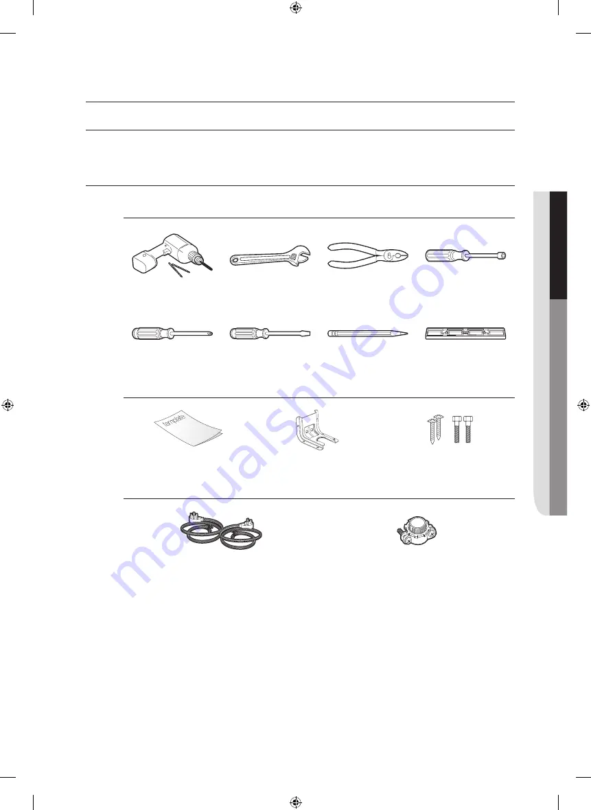
PREPARE LAS HERRAMIENTAS Y LAS PIEZAS

Las herramientas que necesitará.

Taladro

Llave ajustable

Pinzas

Desarmador de caja 

para tuercas de

 1

/

4"

Desarmador Phillips

Desarmador plano

Lápiz

Nivel

Elementos incluidos con su estufa

Plantilla

Ménsula anti inclinación

Tornillos (4 unid.)

Elementos no incluidos con su estufa

Cable de 4 conductores o  

cable de 3 conductores 

(de 40 o 50 AMP,  

aprobados por United Laboratories, Inc. ("UL"))

Sujetador de cables con amortiguador de 

esfuerzo


(únicamente para instalación con conducto)

Español - 3

01


ANTES DE COMENZAR Y PREP

ARA
CIÓN P

ARA INS

TALAR LA ES

TUF
A

Install_30_Electric_Range_USA_DG68-00108G-09_EN+MES.indb   3

2018-07-31     3:48:07

Содержание NE59T4311SG

Страница 1: ...imagine the possibilities Thank you for purchasing this Samsung product Electric Range installation manual Install_30_Electric_Range_USA_DG68 00108G 09_EN MES indb 1 2018 07 31 3 48 02 ...

Страница 2: ...th the consumer Important note to the consumer Keep these instructions for the local electrical inspector s use As when using any appliance generating heat there are certain safety precautions you should follow Be sure your range is installed and grounded properly by a qualified installer or service technician Make sure the wall coverings around the range can withstand the heat generated by the ra...

Страница 3: ...table Wrench Pliers 1 4 Nut Driver Phillips Screwdriver Flat Screwdriver Pencil Level What s included with your range Template Anti Tip Bracket Screws 4 ea What s not included 4 Wire Cord or 3 Wire Cord UL Approved 40 or 50 AMP Strain Relief For Conduit Installation Only English 3 01 BEFORE YOU BEGIN PREPARING TO INSTALL THE RANGE Install_30_Electric_Range_USA_DG68 00108G 09_EN MES indb 3 2018 07 ...

Страница 4: ...le electrical outlet area Minimum dimensions IMPORTANTTo eliminate the risk of burns or fire caused by reaching over heated surface units cabinet storage space located above the surface units should be avoided If cabinet storage is to be provided the risk can be reduced by installing a range hood that projects horizontally a minimum of 5 beyond the bottom of the cabinets 30 30 15 30 minimum cleara...

Страница 5: ...trical Code requires that new construction not existing utilize a 4 conductor connection to an electric range When installing an electric range in new construction follow Steps 2 and 3 for 4 wire connection You must use a 3 wire or 4 wire single phase A C 208Y 120 Volt or 240 120 Volt 60 hertz electrical system If the electrical service provided does not meet the above specifications have a licens...

Страница 6: ...ver Terminal block Specified power supply cord kit rating Range rating watts Specified rating of power supply cord kit amperes Diameter inches of range connection opening 120 240 volts 3 wire 120 208 volts 3 wire Power cord Conduit 8 750 16 500 7 801 12 500 40 or 50A 13 8 11 8 English 6 Install_30_Electric_Range_USA_DG68 00108G 09_EN MES indb 6 2018 07 31 3 48 04 ...

Страница 7: ...wer left and the lower right terminals of the terminal block 1 Remove the 3 lower terminal screws from the terminal block 2 Insert the 3 terminal screws through each power cord terminal ring and into the lower terminals of the terminal block Be certain that the center wire white neutral is connected to the center lower position of the terminal block 3 Tighten screws securely into the terminal bloc...

Страница 8: ...w into the power cord ground wire terminal ring through the ground plate and into the frame of the range 4 Insert the 3 terminal screws removed earlier through each power cord terminal ring and into the lower terminals of the terminal block Be certain that the center wire white neutral is connected to the center lower position of the terminal block Tighten screws securely into the terminal block 5...

Страница 9: ...used location and enclosure of splices etc must conform to good wiring practices and local codes 1 Loosen the 3 lower terminal screws from the terminal block 2 Insert the center bare wire white neutral tip through the bottom center terminal block opening On certain models the wire will need to be inserted through the ground strap opening and then into the bottom center block opening 3 Insert the t...

Страница 10: ...eutral tip through the bottom center of the terminal block opening 5 Insert the two side bare wire tips into the lower left and the lower right terminal block openings 6 Tighten the screws until the wire is firmly secured 35 to 50 inch lbs Do not over tighten the screws since it could damage the wires 7 Go to step 5 and proceed with the installation Ground strap Ground plate White Black Red Neutra...

Страница 11: ...oncrete approximately 21 32 16 5mm NOTE To install Anti Tip bracket release the leveling leg A minimum clearance of 21 32 16 5mm is required between the range bottom and the kitchen floor 1 Locate the bracket using the template The Anti Tip bracket is packaged with a template The instructions include information necessary to complete the installation Read and follow the instructions on the sheet t...

Страница 12: ...lanted to prevent accidental tipping Ground FINALIZING THE INSTALLATION Move range close enough to the opening to plug into the receptacle Slide range into position insuring that the rear left or rear right leg slides under the Anti Tip bracket The range will sit 0 away from the back wall when properly installed Carefully tip the range forward to insure that the Anti Tip bracket engages the back b...

Страница 13: ...imagine las posibilidades Gracias por adquirir este producto Samsung Estufa eléctrica manual de instalación Install_30_Electric_Range_USA_DG68 00108G 09_EN MES indb 1 2018 07 31 3 48 06 ...

Страница 14: ... estas instrucciones para que puedan ser consultadas por el inspector del servicio eléctrico de su localidad Como con cualquier electrodoméstico que genera calor existen ciertas precauciones de seguridad que se deben cumplir Asegúrese de que su electrodoméstico sea correctamente instalado y conectado a tierra por un técnico calificado Asegúrese de que los revestimientos de las paredes alrededor de...

Страница 15: ... Desarmador Phillips Desarmador plano Lápiz Nivel Elementos incluidos con su estufa Plantilla Ménsula anti inclinación Tornillos 4 unid Elementos no incluidos con su estufa Cable de 4 conductores o cable de 3 conductores de 40 o 50 AMP aprobados por United Laboratories Inc UL Sujetador de cables con amortiguador de esfuerzo únicamente para instalación con conducto Español 3 01 ANTES DE COMENZAR Y ...

Страница 16: ...te Dimensiones mínimas IMPORTANTEPara eliminar el riesgo de quemaduras o de incendio provocado por contacto con las unidades sobrecalentadas en superficie debe evitarse colocar gabinetes de almacenamiento por encima de las unidades de superficie Si deben instalarse gabinetes de almacenamiento el riesgo puede reducirse instalando una campana para estufas que se proyecte horizontalmente por lo menos...

Страница 17: ...iones nuevas no existentes en ese momento para estufas de cocina se utilicen conexiones de cuatro conductores Cuando instale una estufa eléctrica en una construcción nueva siga los Pasos 2 y 3 para conexión de 4 conductores Debe usar un sistema eléctrico de 3 o 4 conductores monofásico CA 208Y 120 voltios o 240 120 voltios 60 hertz Si el servicio eléctrico provisto no cumple con las especificacion...

Страница 18: ...es Especificaciones del kit de cable para alimentación eléctrica Especificación de estufa watts Especificaciones del kit de cable para alimentación eléctrica en amperes Diámetro en pulgadas de la abertura para conexión de la estufa 120 240 voltios 3 conductores 120 208 voltios 3 conductores Cable de la alimentación Conducto 8750 16500 7801 12500 40 o 50 A 13 8 11 8 Español 6 Install_30_Electric_Ra...

Страница 19: ...el cuerpo de terminales Los chicotes de cable que portan corriente deben conectarse a las terminales inferior izquierda e inferior derecha del cuerpo de terminales 1 Retire los tornillos de las tres terminales inferiores del cuerpo de terminales 2 Introduzca los 3 tornillos terminales a través de cada aro terminal del cable de alimentación y dentro de las terminales inferiores del cuerpo de termin...

Страница 20: ...e aro de tierra del cable de alimentación también a través de la chapa de conexión a tierra y dentro del marco de la estufa 4 Introduzca los 3 tornillos terminales retirados anteriormente a través de cada aro terminal del cable de alimentación y dentro de las terminales inferiores del cuerpo de terminales Asegúrese de que el conductor central blanco neutro sea conectado a la posición central infer...

Страница 21: ...encapsulamiento de uniones etc deben cumplir con las buenas prácticas de cableado y los códigos locales 1 Afloje los tornillos de las 3 terminales inferiores del cuerpo de terminales 2 Introduzca la punta desnuda del conductor central blanco neutro a través de la abertura en la parte central inferior del cuerpo de terminales En ciertos modelos será necesario introducir el conductor a través de la ...

Страница 22: ...a través de la abertura en la parte central inferior del cuerpo de terminales 5 Introduzca las puntas desnudas de los dos conductores laterales en las aberturas inferior izquierda e inferior derecha del cuerpo de terminales 6 Ajuste los tornillos hasta que los conductores queden firmemente anclados 35 a 50 pulgadas libras de torque No ajuste los tornillos en exceso porque esto podría dañar los con...

Страница 23: ...tornillo debe introducirse en madera o concreto aproximadamente 21 32 pulgadas 16 5 mm NOTA Para instalar la ménsula Anti Inclinación libere la pata niveladora Se requiere una distancia mínima de 21 32 pulgadas 16 5 mm entre la parte inferior de la estufa y el piso de la cocina 1 Ubique la ménsula en la posición adecuada utilizando la plantilla La ménsula anti inclinación se encuentra empacada jun...

Страница 24: ...l vuelco accidental Piso FINALIZACIÓN DE LA INSTALACIÓN Mueva la estufa lo suficientemente cerca de su lugar como para enchufar en el tomacorriente Deslice la estufa a su posición asegurándose de que la pata trasera izquierda o trasera derecha se deslice por debajo de la ménsula anti inclinación Cuando se encuentre bien instalada la distancia entre la estufa y la pared de atrás será de 0 Con cuida...

Отзывы: