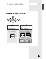
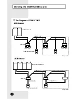
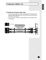
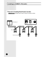
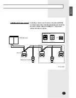

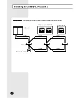
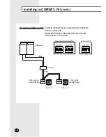

Installing to COM1(F1, F2) (cont.)
E-
8
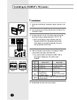
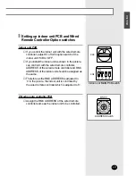
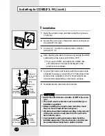
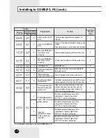
Installation
Open the wired remote controller by using 2 grooves on its
top.
1
Secure the rear cover of the wired remote controller on the
wall with 2 screws.
2
Reassemble the wired remote controller.
5
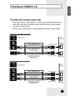
Connect each F1, F2, V1, V2, indoor unit terminal with
the wired remote controller terminal F1, F2, V1, V2.
3
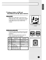
After checking the kind of outdoor unit, assign the DS01
switch SW2 of the indoor unit PCB to ON.
4
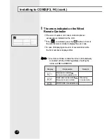
◆
If you set to COM2 and install it to COM1, ‘606’ of
error signs is displayed on the wired remote
controller.
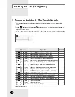
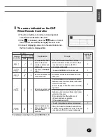
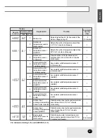
DS01
SW1 SW2 SW3 SW4
SW5 SW6 SW7 SW8
DS02
SW1
SW2
SW3
SW4
SW5
Cooling Only
COM2(F3, F4)
°C
The wired and
wireless remote
controller available
Cooling and Heating
COM1(F1, F2)
°F
Can be used
wired remote controller
only
Switch
No.
Switch OFF
Switch ON
Refer to the chapter ‘Additional Function of the wired
remote controller’.
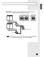
◆
When connecting the communication cable and
the power cable, don’t confuse about each cable.
If the cables are connected improperly, the wired
remote controller will not work.
Содержание MWR-TH00
Страница 33: ...E 33 ENGLISH Memo ...


