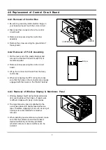
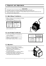
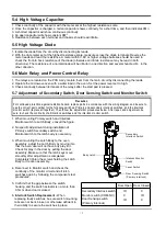
Samsung MW1266WC Скачать руководство пользователя страница 22

- 20 -

8-2 P.C.B Parts List

Code No.

Description

Specification

Q'ty

Remark

3501-001155

RELAY-MINIATURE

24VDC,200MW,3000MA,1FORMA,10MS,10MS

2

RY01,03

3501-001188

RELAY-POWER

24V DC,0.53W,-,1FormA,9.3ms,10mS

1

RY02

3708-001510

CONNECTOR-FPC/FC/PIC

14P,1.25mm,STRAIGHT,SN

1

CN04

DE07-00021K

LED DISPLAY

CSQ-4246G-10,NC2000-CMO,-,40SEG,5DIGIT,-

1

LED1

DE09-00214A

IC MICOM

TMP87CH47U-3DC0,SM-200102-CN,-,-,-,MW850W,-,-

1

IC01

DE26-00037A

TRANS-L.V

SLV-4290U,120V,60Hz,AC17V/7V,-,35*10,PIN,-

1

LVT1

DE30-20016A

BUZZER

CBE2220BA,STICK,-,-,-,-,-,-,-

1

BUZ1

DE92-00784A

ASSY PCB AUTO

120V60HZ,LED,RA-N2LED1-13,-

1

0401-001083

DIODE-SWITCHING

MM4148,100V,150MA,LL-34,TP

15

D08~13,15~23

0402-001103

DIODE-RECTIFIER

1T4,400V,1A,TS-1,TP

7

D01~07

0403-001288

DIODE-ZENER

ZMM55C5V1,4.8-5.4V,500MW,LL-34,TP

1

ZD01

0501-000465

TR-SMALL SIGNAL

MMBT3904,NPN,350mW,SOT-23,TP,100-300

1

TR01

0504-001008

TR-DIGITAL

RN2427,PNP,200MW,2.2K/10K,SOT-23,TP

5

TR09~13

0504-001080

TR-DIGITAL

KRC246S,NPN,200mW,2.2K/10K,SOT-23,TP

4

TR02,03,05,08

1202-000141

IC-VOLTAGE COMP.

7033,SOT-89,3P,-,SINGLE,0V,-,P

1

IC03

1203-001037

IC-VOLTAGE REGULATOR

78L05,SOT-89,3P,185MIL,PLASTIC

1

IC02

1404-001194

THERMISTOR-PTC

39ohm,20%,220/240V,270Vac,1.2A,-,TP

1

PTC1

1405-000001

VARISTOR

470V,1250A,14x7.5mm,TP

1

ZNR1

2007-000033

R-CHIP

0OHM,5%,1/8W,DA,TP,3216

4

J11~13,16

2007-000282

R-CHIP

100KOHM,5%,1/10W,DA,TP,2012

2

R27,28

2007-000300

R-CHIP

10KOHM,5%,1/10W,DA,TP,2012

3

R07,08,09

2007-000346

R-CHIP

120OHM,5%,1/8W,DA,TP,3216

8

R19~26

2007-000468

R-CHIP

1KOHM,5%,1/10W,DA,TP,2012

6

R01,03~05,10,13

2007-000671

R-CHIP

2KOHM,5%,1/10W,DA,TP,2012

1

R02

2007-000931

R-CHIP

470OHM,5%,1/10W,DA,TP,2012

1

R06

2007-000941

R-CHIP

47KOHM,5%,1/10W,DA,TP,2012

5

R14~18

2203-000444

C-CERAMIC,CHIP

1nF,10%,50V,X7R,TP,2012,-

6

C13~17,20

2203-001608

C-CERAMIC,CHIP

22nF,+80-20%,50V,Y5V,TP,2012

4

C09~12

2401-000151

C-AL

1000uF,20%,25V,GP,TP,10x20,5

1

C02

2401-000244

C-AL

100uF,20%,10V,GP,TP,6.3x7,5

1

C03

2401-000911

C-AL

22uF,20%,16V,GP,TP,5x7,5

2

C04,06

2401-002075

C-AL

4.7uF,20%,50V,GP,TP,5x11,5

1

C05

2401-002598

C-AL

220uF,20%,50V,GP,TP,10x16,5

1

C01

2802-000188

RESONATOR-CERAMIC

8MHz,0.5%,TP,10.0x5.0x8.0mm

1

XTL1

3711-000881

CONNECTOR-HEADER

BOX,3P,1R,2.5mm,STRAIGHT,SN

1

CN03

3711-004143

CONNECTOR-HEADER

BOX,2P/3P,1R,5mm/2.5mm,STRAIGH

1

CN02

DE39-60001A

WIRE-SO COPPER

PI0.6,SN,T,52MM,TAPING_WIRE,-,

10

J01~10

DE41-00178A

PCB-MAIN

RA-N2LED1-**,FR-1,1,T1.6*W247*L197,-,4ARRAY,-

1

DE60-60012A

PIN-EYELET

ID2.1,OD2.5,L3.0,SN,BSP,T0.25,

2

Содержание MW1266WC

Страница 1: ...ICROWAVE OVEN 1 Precaution 2 Specifications 3 Operating Instructions 4 Disassembly and Reassembly 5 Alignment and Adjustments 6 Troubleshooting 7 Exploded Views and Parts List 8 PCB Diagrams 9 Schematic Diagrams Manual MW1266WC SILVER ...

Страница 2: ...s and latches 5 evidence of dropping or abuse c Before turning on microwave power for any service test or inspection within the microwave generating compartments check the magnetron wave guide or transmission line and cavity for proper alignment integrity and connections d Any defective or misadjusted components in the interlock monitor door seal and microwave generation and transmission systems s...

Страница 3: ...ould remove their watches while repairing an MWO 11 To avoid any possible radiation hazard replace parts in accordance with the wiring diagram Also use only the exact replacements for the following parts Primary and secondary interlock switches interlock monitor switch 12 If the fuse is blown by the Interlock Monitor Switch Replace all of the following at the same time Secondary door sensing switc...

Страница 4: ...he oven and discharge the high voltage capacitor See Figure 1 1 2 The high voltage capacitor remains charged about 30 seconds after disconnection Short the negative terminal of the high voltage capacitor to to the oven chassis Use a screwdriver 3 High voltage is maintained within specified limits by close tolerance safety related components and adjustments If the high voltage exceeds the specified...

Страница 5: ...NSUMPTION OUTPUT POWER OPERATING FREQUENCY MAGNETRON COOLING METHOD OUTSIDE DIMENSIONS NET WEIGHT SHIPPING WEIGHT 99 MINUTES 99SECONDS 120V CA 60HZ MICROWAVE 1 550W 1100W 10 LEVEL POWER 2 450MHz OM75PH 31 ESS COOLING FAN MOTOR 2019 32 W x 1145 64 H x 161 4 D 33 0 lbs 36 3 lbs ...

Страница 6: ...nstructions 3 1 Control Panel 3 2 Features External Views Door Ventilation Holes Light Safety Interlock Holes Control Pane Open Door Push Button Guide Roller Glass Tray Door Latches CE1D33 523mm 377mm 297mm 249mm 413mm ...

Страница 7: ...hat its antenna does not hit any adjacent parts or it may be damaged NOTE2 When replacing the magnetron be sure to remount the magnetron gasket in the correct position and make sure the gasket is in good condition 4 2 Replacement of High Voltage Transformer 1 Discharge the high voltage capacitor 2 Disconnect all the leads 3 Remove the mounting bolts 4 Reconnect the leads correctly and firmly PRECA...

Страница 8: ... fragile Then remove the door assembly 4 3 2 Removal of Door E Following the procedure as shown in the figure insert and bend a thin metal plate between Door E and Door A until you hear the tick sound 1 Insertion depth of the thin metal plate should be 0 5mm or less 4 3 3 Removal of Key Door Spring Remove pin hinge from Door E Detach spring from Door E and key door Door E Door A Door C ...

Страница 9: ...heck if any other part such as the control circuit board blower motor or high voltage transformer is defective 4 5 Replacement of Drive Motor 1 Take out the glass tray guide roller from cavity 2 Turn the oven upside down to replace the drive motor 3 Remove a screw securing the drive motor cover or disconnect the drive motor cover from base plate by nipper 4 Disconnect all the lead wires from the d...

Страница 10: ...cuit board from the Ass y control box 4 When reconnecting the FPC connector make sure that the holes on the connector are properly engaged with the hooks on the Plastic Fastener 4 6 3 Removal of Window Display Membrane Panel 1 Window display should not be disassembled as its mounting tabs will be broken If repair work is difficult replace with Ass y control panel 2 The membrane key board is attach...

Страница 11: ...lament or shorted magnetron 2 Isolate the magnetron from the circuit by disconnecting its leads 3 A continuity check across the magnetron filament terminals should indicate one ohm or less 4 A continuity check between each filament terminal and magnetron case should read open PRECAUTION 1 High voltage is present at the high voltage terminals during any cook cycle 2 It is neither necessary nor advi...

Страница 12: ... 2 No specific adjustment during installation of Primary switch Secondary switch and Monitor switch to the latch body is necessary 3 When mounting the Latch Body to the oven assembly adjust the Latch Body by moving it so that the oven door will not have any play in it Check for play in the door by pulling the door assembly Make sure that the latch keys move smoothly after adjustment is completed C...

Страница 13: ...y 3 seconds included as a holding time of magnetron oscillation 4 When heating is finished stir the water again with the thermometer and measure the temperature T2 5 Subtract T1 from T2 This will give you the water temperature rise T 6 The output power is obtained by the following formula Output Power 4 187 x 1000 x T 0 55xMcx T2 T0 41 Heating Time sec 38 38 Counting Time sec 4 187 Coefficient for...

Страница 14: ...en at the highest power level 4 Set survey meter dual ranges to 2 450MHz 5 Using the survey meter and spacer cone as described above measure near the opening of magnetron the surface of the air guide and the surface of the wave guide as shown in the following photo but avoid the high voltage components The reading should be less than 4mW cm2 5 11 Note on Measurement 1 Do not exceed the limited sca...

Страница 15: ...n procedure Replace PCB main Timer starts countdown but no microwave oscillation No heat while oven lamp and fan motor turn on 1 Off alignment of latch switches 2 Open or loose connection of high voltage circuit especially magnetron filament circuit NOTE Large contact resistance will bring lower magnetron filament voltage and cause magnetron to lower output and or intermittent oscillation 3 Defect...

Страница 16: ...CB main Loud buzzing noise can be heard 1 Loose fan and fan motor 2 Loose screws on H V Transformer 3 Shorted H V Diode Tighten screws of fan motor Tighten screws of H V Transformer Replace H V Diode Turntable motor does not rotate 1 Open or loose wiring of turntable motor 2 Defective turntable motor Replace turntable motor Oven stops operation during cooking 1 Open or loose wiring of Secondary in...

Страница 17: ...ed Views M002 M001 M049 M056 M051 M015 W002 M099 M039 M040 M042 M038 T001 T017 M034 M132 M048 M020 M029 M035 M036 M037 B018 B006 B001 B004 B009 B002 C082 D049 D007 C007 C006 C004 C005 C009 C003 C001 D011 D006 D005 D004 D015 D002 D003 M018 M019 M031 ...

Страница 18: ...029 DE47 20033A THERMOSTAT PW 2N 80 70 125V15A 250V7 5A 1 M031 DE47 20194C THERMOSTAT PW2N 75C 65C 30 0 1 CAVITY M034 DE67 00106A COUPLER PPS 8g BRN MW1250WA NC 1 2 1 M035 OM75P 31 ESS ASSY MAGNETRON OM75P 31 ESS 1 M036 4713 001102 LAMP INCANDESCENT 125V 25W TRP 25x 1 CV AIR M037 DE71 00164A COVER AIR MW1250WA NC 12 PP TB53 T1 7 1 M038 DE26 00061B TRANS H V SHV U11KA_R 120V 60HZ 2300V 3 1 M039 250...

Страница 19: ... 40175A WINDOW DISPLAY 5G SAN SMG 1 C082 DE94 00538J ASSY CONTROL BOX 120V60Hz MW1266WC XAX W 1 S N A D002 DE64 00185A DOOR A NC2000 1 ABS HR0370 P WHT 1 D003 DE63 00042A SCREEN DOOR CLEAR MW1250WA NC 12 PET T0 1 D004 DE94 00428A ASSY DOOR E COATING MW1250WA NC 12 BLK 1 D005 DE64 00248A FILM DOOR PE PC T0 15 178 5 306 1 D006 DE64 00184A DOOR C MW1250WA PP BLK 1 2CUFT NC200 1 D007 DE61 00193A SPRIN...

Страница 20: ... SCREW A 2S 4X12 TOOTHED 2 CN BOX DE60 10082H SCREW A 2S 4X12 TOOTHED 1 CV AIR DE60 10082H SCREW A 2S 4X12 TOOTHED 2 MGT TCO DE60 10082H SCREW A 2S 4X12 TOOTHED 2 MO FAN DE60 10082H SCREW A 2S 4X12 TOOTHED 1 P C EA DE60 10082H SCREW A 2S 4X12 TOOTHED 3 PN OUT DE60 10082H SCREW A 2S 4X12 TOOTHED 1 S M EA DE60 10098A SCREW ASSY TAP TITE GLD SWRCH18A ZPC2 PH TC M4X8 WT 2 M DRIV DE60 10195A SCREW STAR...

Страница 21: ... 19 8 P C B Diagrams 8 1 P C B Diagrams ...

Страница 22: ...02 1404 001194 THERMISTOR PTC 39ohm 20 220 240V 270Vac 1 2A TP 1 PTC1 1405 000001 VARISTOR 470V 1250A 14x7 5mm TP 1 ZNR1 2007 000033 R CHIP 0OHM 5 1 8W DA TP 3216 4 J11 13 16 2007 000282 R CHIP 100KOHM 5 1 10W DA TP 2012 2 R27 28 2007 000300 R CHIP 10KOHM 5 1 10W DA TP 2012 3 R07 08 09 2007 000346 R CHIP 120OHM 5 1 8W DA TP 3216 8 R19 26 2007 000468 R CHIP 1KOHM 5 1 10W DA TP 2012 6 R01 03 05 10 1...

Страница 23: ...ENSING SWITCH BOTTOM MONITOR SWITCH CENTER BLK WHT SECONDARY SWITCH TOP HIGH VOLTAGE CAPACITOR RED ORG WHT SYMBOL COLOR BLU BLK RED ORANGE WHITE BLUE BLACK WARNING NOTE CIRCUIT SHOWN WITH DOOR IS OPENED POSITION NOTE FOR SERVICE REPLACEMENT USE 16 GA 105 C THERMOPLASTIC COVERED WIRE EXCEPT FOR HIGH VOLTAGE LEADS OR AS NOTED ON SPECIAL LEADS POWER MUST BE DISCONNECTED BEFORE SERVICING THIS APPLIANC...

Страница 24: ...ELECTRONICS Samsung Electronics Co Ltd May 2003 Printed in Korea Code No DE68 03137A ...

Отзывы: