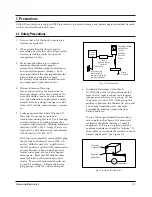
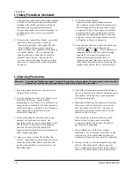
background image

Samsung Electronics

1-3

1-3 Precautions for Electrostatically Sensitive Devices (ESDs)

1-4 Special Precautions and Warning Labels for Laser Products

1. Some semiconductor ("solid state") devices

are easily damaged by static electricity. 
Such components are called Electrostatically
Sensitive Devices (ESDs).  Examples include
integrated circuits and some field-effect 
transistors. The following techniques will
reduce the occurrence of  component 
damage caused by static electricity.

2. Immediately before handling any 

semiconductor components or assemblies,
drain the electrostatic charge from your 
body by touching a known earth ground.
Alternatively, wear a discharging
wrist-strap device.  (Be sure to remove it
prior to applying power--this is an electric
shock precaution.)

3. After removing an ESD-equipped assembly,

place it on a conductive surface such as 
aluminum foil to prevent accumulation of
electrostatic charge.

4. Do not use freon-propelled chemicals.  

These can generate electrical charges that
damage ESDs.

5. Use only a grounded-tip soldering iron

when soldering or unsoldering ESDs.

6. Use only an anti-static solder removal 

device. Many solder removal devices are
not rated as "anti-static" (these can 
accumulate sufficient electrical charge to
damage ESDs).

7. Do not remove a replacement ESD from its 

protective package until you are ready to
install it. Most replacement ESDs are
packaged with leads that are electrically
shorted together by conductive foam,
aluminum foil or other conductive
materials.

8. Immediately before removing the protective

material from the leads of a replacement
ESD, touch the protective material to the
chassis or circuit assembly into which the
device will be installed.

9. Minimize body motions when handing

unpackaged replacement ESDs. Motions
such as brushing clothes together, or lifting
a foot from a carpeted floor can generate
enough static electricity to damage an ESD.

Precautions

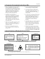
UL     : Manufactured for U.S.A. Market.
CSA  : Manufactured for Canadian Market.
EU 

: Manufactured for European Market.

SCAN : Manufactured for Scandinavian 

Market.

This Product Complies with
DHHS Rules 21CFR, Sub 
chapter J.At date of Manu-
facture

(UL)

(UL,CSA,SCAN)

(EU)

CERTIFIED ONLY TO CANADIAN
ELECTRICAL CODE. 

CERTIFIE EN VERTU DU CODE
CANADIAN DE LELETRICITE
SEULEMENT

(CSA)

CLASS 1
LASER PRODUCT

(UL,CSA,EU)

Fig. 1-3  Warning Labels  (Location: Enclosure Block)

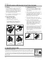
Fig. 1-4   Warning Labels  (Location: Disc Clamper,  Inner Side of Unit Door or Nearby Unit Chassis )

CAUTION : 

INVISIBLE LASER RADIATION WHEN OPEN 

AND INTERLOCKS DEFEATEO AVOIDEXPOSURE TO BEAM

ADVARSEL:

USYNLIG LASERSTRÅLING VED ABNING

NÅR SIKKERHEDSAFBRYDERE ER UDE AF FUNKTION

UNDGA UDSAETTELSE FOR STRALING

VARO:

AVATTAESSA JA SUOJALUKITUS OHITETTAESSA 

OLET ALTTINA NAKYMATTÖMALLE LASERSATEILYLLE ALA
KATSO SATEESEEN!

VARNING:

OSYNLIG LASERSTRÅLNING NAR DENNA DEL 

AR OPPNAD OCH SPARREN AR URKOPPLAD BETRAKTA
EJSTRÅLEN!

Содержание MM-X7

Страница 1: ...MICRO COMPONENT SYSTEM BASIC MODEL MM X7 DX7 KX7 SERVICEManual MICRO COMPONENT SYSTEM Features MP3 CD DVD CD R RW Playback USB HOST Tuner Confidential...

Страница 2: ...rent for Appliances and Underwriters Laboratories UL Publication UL1410 59 7 With the unit completely reassembled plug the AC line cord directly into a 120V AC outlet With the unit s AC switch first i...

Страница 3: ...plug the unit s AC power cord from the AC power source before attempting to a Remove or reinstall any component or assembly b Disconnect an electrical plug or connector c Connect a test component in p...

Страница 4: ...eady to install it Most replacement ESDs are packaged with leads that are electrically shorted together by conductive foam aluminum foil or other conductive materials 8 Immediately before removing the...

Страница 5: ...plane which is grounded 3 The repair technician must wear a wrist strap which is grounded to the copper sheet 4 To remove the Optical Pickup block Place the set on the conductive sheet and momentaril...

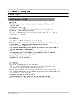
Страница 6: ...n disc the disc can be played only up to the blank segment A maximum of 9 999 images can be stored on a single CD When playing a Kodak Fuji Picture CD only the JPEG files in the picture folder can be...

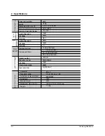
Страница 7: ...tio Channel separation Input sensitivity G E N E R A L T U N E R F M T U N E R MW VIDEO OUTPUT A M P L I F I E R 60W 4 3Kg 170 x 175 x 292 mm 5 C 35 C 10 75 10dB 55dB 0 8 56dB 40dB 2 1 0Vp p 75 load Y...

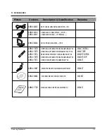
Страница 8: ...X7 KOREA AH59 01787E REMOCON ASSY MM X7 NOEUR SAMSUNG 172 48 MM X7 EXP AH59 01787A REMOCON ASSY MM DX7 KOR SAMSUNG 237 48 MM DX7 KOREA AH59 01787B REMOCON ASSY MM DX7 NOEUR SAMSUNG 237 48 MM DX7 EXP...

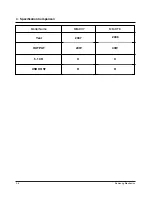
Страница 9: ...2 4 Samsung Electronics 4 Specification Comparison MM DX7 Model Name MM DT8 2006 2007 Year 40W 20W X X 5 1 CH OUTPUT O O USB HOST...

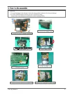
Страница 10: ...Samsung Electronics 3 1 3 How to disassemble...

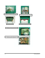
Страница 11: ...3 2 Samsung Electronics...

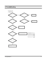
Страница 12: ...Samsung Electronics 4 1 4 TroubleShooting...

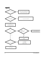
Страница 13: ...4 2 Samsung Electronics...

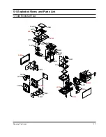
Страница 14: ...xploded Views and Parts List 1 Total Exploded View AD150 AD300 AW120 AC010 HOLD LENS SHEET AC020 AC050 AC070 AC330 TJ1 HEAT AB120 AB130 AL002 AD005 AS260 AH155 AD450 AK420 AL210 AK250 AC320 AK130 MICG...

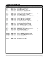
Страница 15: ...B CABINET SIDE L MM DX7 ABS W242 L1 AC070 AH64 04228B CABINET SIDE R MM DX7 ABS W242 L1 AD150 AH64 04223B DECORATION FRONT MM X7 ABS W170 L X AD300 AH64 04232A DECORATION RING MM DX7 ABS X AD450 AH64...

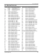
Страница 16: ...IC MLC AXIAL 10NF 30 16V Y5S TP FC12R 2202 000797 C CERAMIC MLC AXIAL 10NF 30 16V Y5S TP FC13 2401 000042 C AL 100uF 20 16V GP TP 6 3x7 5 FC1L 2203 000595 C CER CHIP 0 22nF 5 50V C0G 2012 FC1R 2203 00...

Страница 17: ...CERAMIC DISC 47nF 80 20 12 5x4m RC15 2201 000161 C CERAMIC DISC 10NF 80 20 500V Y5V TP RC2 2401 001633 C AL 6800uF 20 25V GP BK 18x35 5 7 RC4 2401 001052 C AL 3300uF 20 25V GP 16x31 5 7 RC5 2401 00080...

Страница 18: ...00981 R CHIP 5 6Kohm 5 1 8W TP 2012 HR5R 2007 000981 R CHIP 5 6Kohm 5 1 8W TP 2012 HR6L 2007 000338 R CHIP 120Kohm 5 1 8W TP 2012 HR6R 2007 000338 R CHIP 120Kohm 5 1 8W TP 2012 HR8L 2007 000282 R CHIP...

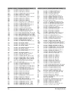
Страница 19: ...0501 000341 TR SMALL SIGNAL KSC1623 L NPN 200mW SOT UR1 2007 000290 R CHIP 100ohm 5 1 8W TP 2012 UR101 2007 000468 R CHIP 1Kohm 5 1 8W TP 2012 UR103 2007 000565 R CHIP 220Kohm 5 1 8W TP 2012 UR111 200...

Страница 20: ...10 16V X7R 1608 MC36 2203 005148 C CER CHIP 100nF 10 16V X7R 1608 MC37 2203 005148 C CER CHIP 100nF 10 16V X7R 1608 MC38 2203 005148 C CER CHIP 100nF 10 16V X7R 1608 MC39 2203 005148 C CER CHIP 100nF...

Страница 21: ...000236 C CER CHIP 0 1nF 5 50V C0G 1608 RC13 2203 000189 C CER CHIP 100nF 80 20 25V Y5V 1608 RC14 2402 001096 C AL SMD 220UF 20 16V GP TP 6 6X6 6X7 RC16 2203 001652 C CER CHIP 470nF 80 20 16V Y5V 1608...

Страница 22: ...RR90 2007 000102 R CHIP 100Kohm 5 1 10W TP 1608 RR92 2007 000102 R CHIP 100Kohm 5 1 10W TP 1608 SCREW1 6003 001464 SCREW TAPTITE BH B M3 L10 ZPC WHT TC5 2402 001096 C AL SMD 220UF 20 16V GP TP 6 6X6 6...

Страница 23: ...Samsung Electronics 6 1 6 1 Wiring Diagram...

Страница 24: ...6 2 Samsung Electronics 6 2 PCB Diagram 1 MAIN FIC1 21PIN CLOCK FIC1 22PIN DATA FIC1 26 27PIN AUDIO SIGNAL...

Страница 25: ...Samsung Electronics 6 3 2 FRONT UIC1 15 16PIN 10MHz CRYSTAL UIC1 12 13PIN 32 768KHz CRYSTALS...

Страница 26: ...Samsung Electronics 7 1 This Document can not be used without Samsung s authorization 7 1 Block Diagram 1 MAIN Part...

Страница 27: ...7 2 Samsung Electronics This Document can not be used without Samsung s authorization 7 2 Schematic Diagram 1 1 MAIN 1 MICOM CLOCK 2 MICOM DATA 3 AUDIO SIGNAL 4 VIDEO SIGNAL...

Страница 28: ...Samsung Electronics 7 3 This Document can not be used without Samsung s authorization 4 3 2 1 2 1 FRONT 1 10MHz CRYSTAL 1 32 768KKHz CRYSTAL 3 AUDIO SIGNAL 4 VIDEO SIGNAL...

Страница 29: ...Document can not be used without Samsung s authorization 8 1 MAIN MICOM and MPEG MICOM communication MPEG PCB 1 MAIN MICOM TO MAIN MICOM FE 1 U TXD waveform 2 U STB waveform 3 U RXD waveform 4 U ACK...

Страница 30: ...8 2 Samsung Electronics This Document can not be used without Samsung s authorization 8 2 Servo MPEG PCB...

Страница 31: ...d without Samsung s authorization 8 3 Video output MPPEG PCB VIDEO_Y VIEDO_PB and VIDEO_PR is component video output CVBS1 is composite video output LA73054 is video driver IC 1 CVBS1 waveform 1 VIDEO...

Страница 32: ...8 4 Samsung Electronics This Document can not be used without Samsung s authorization 4 PCB IC A SIDE...

Страница 33: ...Samsung Electronics 8 5 This Document can not be used without Samsung s authorization B SIDE...

Отзывы: