Samsung Electronics
4-2
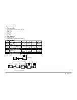
Step
Item
Connection
SSG.FREQ.
FREQ. Setting
Adjust. Point
Remark
Maximum
output
Maximum output
Maximum output
1
Intermediate
frequency (IF)
adjustment
AM frequency
coverage
adjustment
Figure 4-5
Figure 4-4
Connect DC
voltmeter to TCON1
and GND(TP1)
522 KHZ
522 KHZ
IT 2
OT 1
OCT 2
OL 1
OCT 1
9V
0.9V
522 KHZ
594 KHZ
1404 KHZ
1611 KHZ
594 KHZ
1404 KHZ
Figure 4-5
_
_
_
Repeat step 2 and 3 serveral times
Repeat step 5 and 6 several times
AM tracking
adjustment
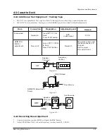
Figure 4-4 AM Frequecny Coverage Adjustment
Figure 4-5 AM Tracking Adjustment
SET
TP2
DC Voltmeter
Input
TP1
AM Signal
Generator
Test Loop
Antenna
AM
Loop Antenna
Jack
Speaker
terminal
GND
Oscilloscope
VTVM
IN
OUT
SET
60 cm
Alignment and Adjustments
2
3
4
5
6
7
4-1-1 Test Equipment
1. AM Standard Signal Generator (S.S.G) : 400Hz, 30% MOD
2. Oscilloscope
3. VTVM
4. Frequency counter
5. Loop antenna
6. Dummy load (4½)
7. DC voltmeter
4-1-2 Pre-Adjustment
1. Check the source voltage.
2. Set function and band switches to the band to be aligned.
3. Set the equalizer, volume and balance controls to mid position.
4-1-3 AM Adjustment
Содержание MM-16
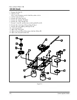
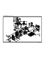
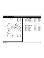
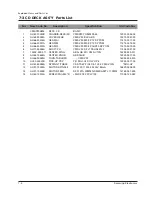
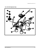
Страница 24: ...Samsung Electronics 7 5 Exploded Views and Parts List 7 3 1 CD DECK Exploded View ...
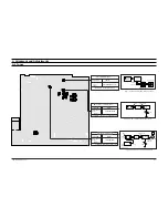
Страница 33: ...Samsung Electronics 9 1 IIC1 UIC1 JIC1 AIC1 UIC2 LC72362 PLL CD MICOM 9 Block Diagrams 9 1 Main ...
Страница 40: ...Block Diagrams KS9282 DSP NIC9282 9 8 Samsung Electronics ...
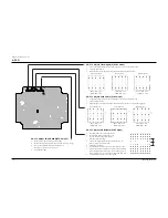
Страница 43: ...10 PCB Diagrams 10 1 Main 10 1 Samsung Electronics ...
Страница 44: ...Samsung Electronics 10 2 10 2 Front PCB Diagrams ...
Страница 45: ...10 3 Samsung Electronics 10 3 CD 10 3 1 Top View 10 3 2 Bottom View PCB Diagrams ...
Страница 46: ...11 1 Samsung Electronics 11 Wiring Diagram ...


