background image

©

Samsung Electronics Co., Ltd. Aug. 1996.

Code No.  AH68-20128A

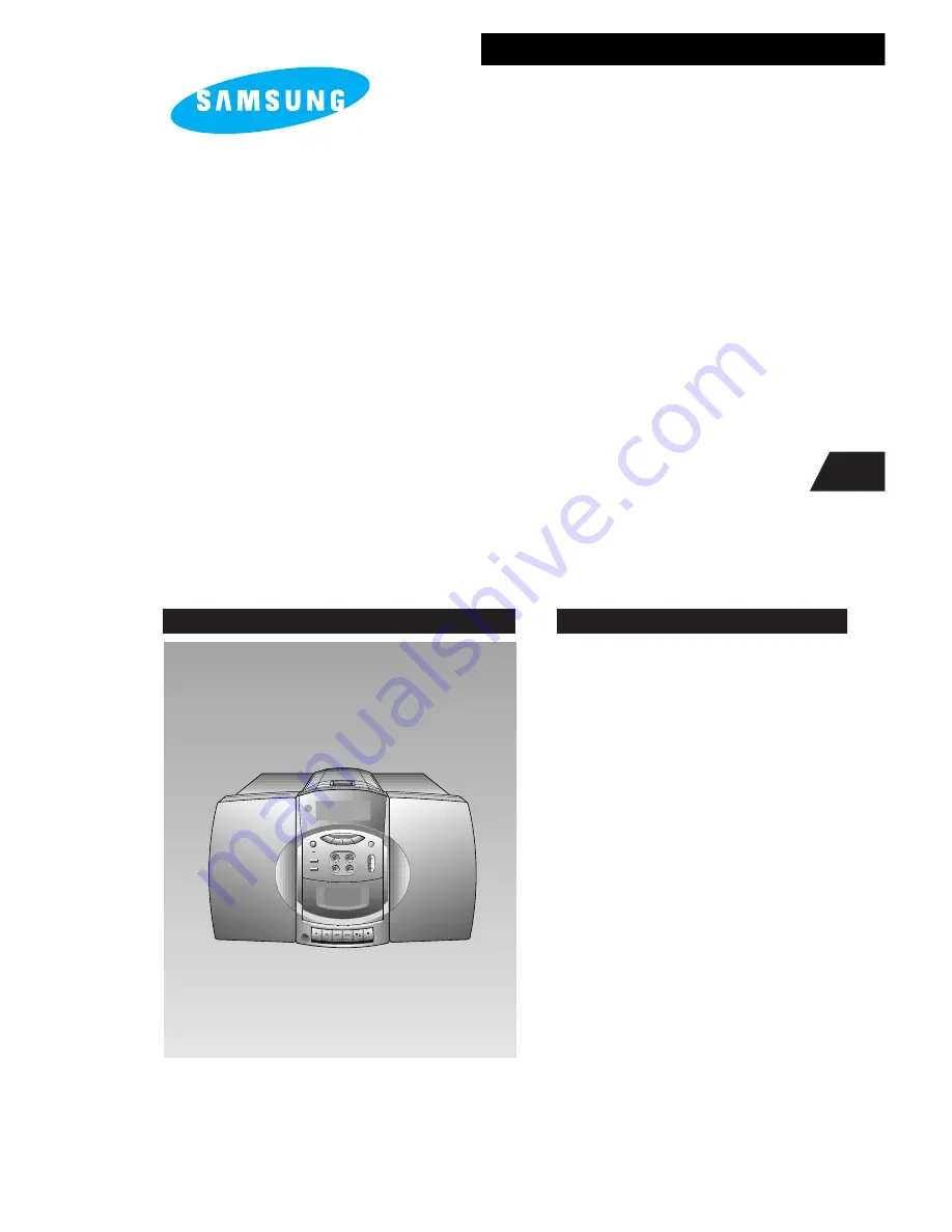
MICRO COMPONENT SYSTEM

1. Precautions

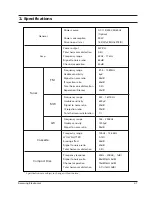
2. Specifications

3. Disassembly and Reassembly

4. Alignment and Adjustments

5. Special Circuit Descriptions

6. Troubleshooting

7. Exploded Views and Parts List

8. Electrical Parts List

9. Block Diagrams

10. PCB Diagrams

11. Wiring Diagram

12. Schematic Diagrams

POWER

SUPER BASS

VOLUME

DOWN                      UP

ON/STANDBY

CD REPEAT  A 

 B

PHONEG

EQ PRESET

TAPE

CD

BAND

TUNER

AUX

TUNING

SERVICE 

Manual

MICRO COMPONENT
SYSTEM

MM-16

CONTENTS

Содержание MM-16

Страница 1: ...t and Adjustments 5 Special Circuit Descriptions 6 Troubleshooting 7 Exploded Views and Parts List 8 Electrical Parts List 9 Block Diagrams 10 PCB Diagrams 11 Wiring Diagram 12 Schematic Diagrams POWER SUPER BASS VOLUME DOWN UP ON STANDBY CD REPEAT A B PHONEG EQ PRESET TAPE CD BAND TUNE R AU X TUNING SERVICEManual MICROCOMPONENT SYSTEM MM 16 CONTENTS ...

Страница 2: ...rrent for Appliances and Underwriters Laboratories UL Publication UL1410 59 7 With the unit completely reassembled plug the AC line cord directly into a 120V AC outlet With the unit s AC switch first in the ON position and then OFF measure the current between a known earth ground metal water pipe etc and all exposed metal parts Examples Handle brackets metal cabinets screwheads and control shafts ...

Страница 3: ...nplug the unit s AC power cord from the AC power source before attempting to a Remove or reinstall any component or assembly b Disconnect an electrical plug or connector c Connect a test component in parallel with an electrolytic capacitor 3 Some components are raised above the printed circuit board for safety An insulation tube or tape is sometimes used The internal wiring may be clamped to preve...

Страница 4: ...ou are ready to install it Most replacement ESDs are packaged with leads that are electrically shorted together by conductive foam aluminum foil or other conductive materials 8 Immediately before removing the protective material from the leads of a replacement ESD touch the protective material to the chassis or circuit assembly into which the device will be installed 9 Minimize body motions when h...

Страница 5: ...tical Pickup Follow this procedure 2 Place a conductive sheet on the work bench i e the black sheet used for wrapping repair parts Note The surface of the work bench should be covered by a copper ground plane which is grounded 3 The repair technician must wear a wrist strap which is grounded to the copper sheet 4 To remove the Optical Pickup block Place the set on the conductive sheet and momentar...

Страница 6: ...monic distoration Frequency range Usable sensivity Signal to noise ratio Frequecny range WOW FLUTTER Erasing effect Signal to noise ratio Total harmonic distortion Frequency response Signal to noise ratio Channel separation Total harmonic distortion 87 5 108MHz 6µV 55dB 60dB 0 5 25dB 522 1611KHz 600µV 40dB 30dB 1 146 290KHz 1200µV 35dB 125Hz 12 5KHz 0 15 50dB 40dB 2 5 20Hz 20KHz 1dB 85dB 1kHz 0dB ...

Страница 7: ...mote Control EQ PRESET MUTE MONO ST AUX POWER PLAY PAUSE VOLUME TUNING TUNING INTRO RANDOM MEMORY BAND SLEEP PRESET MANUAL CLOCK TIMER TUNER SKIP SEARCH STOP REPEAT DISPLAY PROGRAM TAPE CD VOLUME FUNCTION ...

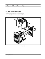
Страница 8: ... and Reassembly 3 1 Cabinet Top Cabinet Rear 1 Remove 8 screws of and 5 screws of of its rear part 2 Pull its top part upward vertically as shown in the figure 3 1 1 1 1 1 2 2 2 2 Samsung Electronics 3 1 Figure 3 1 ...

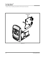
Страница 9: ...3 2 Main PCB 1 Remove 1 screw of and pull out the Main PCB backward horizontally 3 2 Samsung Electronics 1 Main PCB Figure 3 2 Disassembly and Reassembly ...

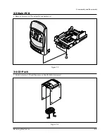
Страница 10: ...4 CD Pack 1 Undo 4 screws of and then remove the CD Pack downward 3 3 Main PCB 1 Remove 3 screws of and pull it out backward 1 Samsung Electronics 3 3 Figure 3 3 Figure 3 4 1 1 Disassembly and Reassembly ...

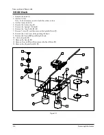
Страница 11: ...move the Turn Table M 7 Remove 2 screw and then remove the Spindle Motor 8 Remove the Cover Gear by pushing the hook 9 Remove the Gear c by pushing the hook 10 Lift the Gear b 1 11 Remove the Gear a 2 12 Remove 2 screws 3 and then remove the Feed Motor 4 13 Remove the Chassis Deck M 5 4 6 7 13 2 1 9 10 11 12 14 15 8 3 5 3 4 Samsung Electronics Figure 3 5 Disassembly and Reassembly ...

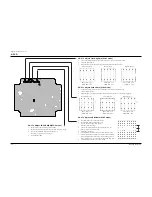
Страница 12: ... Input Input Figure 4 1 IF CENTER and T H D Adjustment Figure 4 2 FM Auto Search Level Adjustment Output Distortion Meter Oscilloscope Oscilloscope FM antenna FM SSG FM SSG GND 26dB 75Ω Dummy 75Ω Dummy FM IN FM Antenna SET 50 kB SET Output GND FM Stereo Adjustment SSG FREQ 98MHz Adjustment point SEMI VR 5KB ISVR2 L CH R CH Maximum Figure 4 3 Figure 4 3 FM Stereo Separation Adjustment EXT FM SSG St...

Страница 13: ...veral times AM tracking adjustment Figure 4 4 AM Frequecny Coverage Adjustment Figure 4 5 AM Tracking Adjustment SET TP2 DC Voltmeter Input TP1 AM Signal Generator Test Loop Antenna AM Loop Antenna Jack Speaker terminal GND Oscilloscope VTVM IN OUT SET 60 cm Alignment and Adjustments 2 3 4 5 6 7 4 1 1 Test Equipment 1 AM Standard Signal Generator S S G 400Hz 30 MOD 2 Oscilloscope 3 VTVM 4 Frequenc...

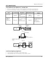
Страница 14: ...utton 2 Adjust KT431 Bias OSC Coil until frequency counter reads 85 0 2KHz Item Connection Preparation Tape speed Figure 4 6 Figure 4 8 3 KHz SVR Inside motor AZIMUTH DECK adjustment Maximum output and identical phase of L R channel Set the screw after adjustment Insert MTT 111 to Deck Press PLAY button Insert MTT 113CN to Deck Press PLAY button Figure 4 7 AZIMUTH Adjustment Screw REC PB Head Osci...

Страница 15: ...e to Vref and terminal to TP1 2 Load and play the disc 3 While the disc is running adjust the gain with NVR1703 as shown in the following figure VOLT DIV 0 2V TIME DIV 2mS Normal frequency Normal frequency Low frequency High frequency Low frequency High frequency VOLT DIV 0 1V TIME DIV 2mS VOLT DIV 0 1V TIME DIV 2mS VOLT DIV 0 1V TIME DIV 2mS VOLT DIV 0 2V TIME DIV 2mS VOLT DIV 0 2V TIME DIV 2mS 1...

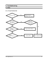
Страница 16: ... No Yes No Yes No No Yes LCD lamp is ON Power Transistor RQ705 fuse normal Pins 73 31 of UIC1 LC72362 is at 5V Connection and soldering of SCON1 UCON1 are normal Check Voltage at RIC1 Replace RQ702 RQ703 Replace RQ701 Voltages at RQ702 RQ703 are normal Voltage at RQ701 is normal ...

Страница 17: ... is at 1 5V 0 5 on low coverage 7 5V 0 5 on high coverage Replace FET Voltage at FET are normal Yes No No Check pump charge circuitry OQ5 connection of SCON1 UCON1 soldering of pin77 of LC72362N Yes Voltage at LA1851N IIC1 and tuner semi conductors are normal Refer to Schematic Diagram Voltage between TCON1 AM MW Low coverage 0 9V 0 1 High coverage 9V 0 5 LW Low coverage 0 7V 0 1 High coverage 4 5...

Страница 18: ...oise occurs at pin3 22 with volume control at mid position Noise occurs at pins1 24 Check function selector section 6 1 4 Tape Not Playing 6 1 5 Audio Output Problem No Yes Yes Yes No Speaker connections are normal all pins of AIC1 TA8207 are normal Refer to Schematic Diagram Voltage at base of AQ601 AQ651 C945 is less than 0 6V Pattern Speaker Jack normal Check power supply section Check Muting c...

Страница 19: ...ck oscillation of NXF100 16 9344MHz Does Laser function during Focus Search Replace PICK UP Check NIC9282 pin73 voltage Replace NIC9282 Yes POWER ON Check Door S W Replace NIC9220 or NIC9258 during Focus Search 5V Yes Yes No No No No Yes Yes 6 2 CD 6 2 1 Malfunction of DISC Revolution Troubleshooting ...

Страница 20: ...conditon Check waveform of NIC9270 pins 9 12 Check waveform of NIC9270 Replace NIC05 Check Amp operation Malfunction of Audio output pins 19 20 Replace NIC9270 Check NIC9270 soldering condition Replace NIC9270 Check NIC9270 soldering condition Yes Yes Yes Yes Yes No No No pins 2 19 6 2 2 Malfunction of Audio output ...

Страница 21: ...ND SLEEP PRESET MANUAL CLOCK TIMER TUNER SKIP SEARCH STOP REPEAT DISPLAY PROGRAM TAPE CD VOLUME FUNCTION 31 36 35 37 34 33 32 38 40 39 44 43 41 26 27 28 11 12 13 14 48 25 24 46 19 10 20 21 22 23 18 17 49 50 52 47 51 4 5 6 7 3 2 1 30 29 15 16 9 8 Exploded Views and Parts List 7 2 Main Exploded View and Parts List ...

Страница 22: ... M REC SAFETY LEVER EJECT LEVER F CAM GEAR F F GEAR SENSOR ARM LEAF SW MAIN R P HEAD E HEAD BELT MAIN BELT SUB BUTTON KNOB ADR2083FRU 51299 02506XC ADR28 010 ADR26 001 ADR02 042 ADR15 021 EG530AD 2B ADR22 012 11128 00045AA 11116 00011AA 11116 00011AA 11105 00031AA 11134 01000AA 11134 01220AA 11128 00393AA 11128 00055AA 11102 00530AA MSW1541 X ACV MS15RA A2N1 PHK380 MS16A Ø45 5 X T1 0 Ø34 7PI X T1 ...

Страница 23: ...AR A GEAR B GEAR C SHAFT PU CENTER RING CENTER KNOB TURN TABLE M PICK UP CDP SPRING T TABLE MOTOR SPINDLE MOTOR FEED SCREW PH M2 3 BASIC CMSP30 POM M90 44 CMS V30 BLK ABS CMS V30 M0 3 Z13 SP POM CMS V30 M0 3 Z13 SP POM CMS V30 M0 3 Z16 Z90 SP POM CMS V30 D3 L79 SUS420J2 ABS GS 20 CMS V10N ABS 94HB CMS V30 P U SOH A1 ROW V P J CS STS W PI0 4 D5 7 L9 3 CMS V10N RF 310T 11400 43L 25V 85mA RF 310TA 30...

Страница 24: ...Samsung Electronics 7 5 Exploded Views and Parts List 7 3 1 CD DECK Exploded View ...

Страница 25: ... PMMA T10 0 7X15 PMMA T10 0 7X15 PMMA T10 0 7X15 SUS T1 0 ABS 94HB TRP ADR2083FRU CASSETTE ABS 94HB BLK ABS 94HB BLK ABS 94HB BLK ABS 94HB BLK ABS 94HB BLK ABS 94HB BLK ABS 94HB BLK ABS 94HB BLK ABS 94HB BLK ABS 94HB BLK 28 29 30 31 32 33 34 35 36 37 38 39 40 41 43 44 46 47 48 49 50 51 52 53 FILTER LCD LEVER EJECT LEAF SW CABINET TOP SPRING EJECT KNOB CD EJECT SHEET CHUCK DOOR CD WINDOW CD DOOR CH...

Страница 26: ...1 8X 11018 877 392 UR6 7 19 21 2001 000734 R CARBON 4 7KOHM 5 1 8W AA TP 1 8X 11018 877 472 UR16 18 20 25 34 35 42 43 2001 000786 R CARBON 47KOHM 5 1 8W AA TP 1 8X3 11018 877 473 UR1 2 3 4 5 2001 000855 R CARBON 560OHM 5 1 4W AA TP 2 4X6 11018 257 561 UR31 2001 000977 R CARBON 8 2KOHM 5 1 8W AA TP 1 8X 11018 877 822 UC1 2 2201 000273 C CERAMIC DISC 18PF 5 50V NPO 5 0 11407 057 180 UC5 2201 000300 ...

Страница 27: ... 9 1V 8 5 9 6V 1 12169 403 340 OVD1 0405 000138 DIODE VARACTOR KV1236 20V 100NA TO 12169 501 005 JQ301 351 302 352 CQ806 0501 000010 TR SMALL SIGNAL KSC1008 Y NPN 80V 6 12149 301 050 RQ703 UQ903 CQ805 808 0501 000294 TR SMALL SIGNAL PNP 800MW TO 92 T 12149 101 560 OQ4 IQ2 0501 000303 TR SMALL SIGNAL PNP 250MW TO 92 12149 101 520 IQ1 0501 000392 TR SMALL SIGNAL NPN 250MW TO 92 12149 301 860 KQ431 0...

Страница 28: ... TP 2 4X6 11018 277 220 KR433 2001 000527 R CARBON 22OHM 5 1 8W AA TP 1 8X3 11018 877 220 OR7 IR21 2001 000548 R CARBON 270KOHM 5 1 8W AA TP 1 8X 11018 877 274 AR606 656 2001 000552 R CARBON 270OHM 5 1 4W AA TP 2 4X6 11018 277 271 IR13 14 2001 000563 R CARBON 27KOHM 5 1 8W AA TP 1 8X3 11018 877 273 IR9 15 16 KR434 2001 000591 R CARBON 3 3KOHM 5 1 8W AA TP 1 8X 11018 877 332 RR722 2001 000611 R CAR...

Страница 29: ... 2 5MM ST FJ1 3716 000197 TERMINAL BLOCK NON SOLDER 2P 4MM A3059 0014 AJ1 3716 000209 TERMINAL BLOCK 60V 7A 13303 500 620 QJ1 3722 000377 JACK RCA 4P 2C 3 5MM SN BLK 16 22 A3040 0218 AJ2 3722 000495 JACK PHONE 11P 3 5MM AG IIC1 AH14 10002D IC LA1851N IT1 AH26 10001C TRANS IF KS940228 10 FM 7 6X12 0 12619 020 067 IT2 AH26 10001E TRANS IF KS940228 09 7 6X12 0 12619 030 005 OT2 AH26 10001J TRANS IF K...

Страница 30: ... 11505 714 154 FTZ1 4 QC515 565 2301 000390 C FILM PEF 15NF 10 50V 6 5X9X3 5MM IC7 2301 000393 C FILM PEF 18NF 10 50V 6 5X12 5X3 KC434 2301 000400 C FILM PEF 1NF 10 50V 5X7X2 8MM 5M JC306 356 QC510 560 517 2301 000412 C FILM PEF 22NF 10 50V 6 5X10 5X4M QC567 OC11 2301 000419 C FILM PEF 27NF 10 50V 7 5X10 5X4M IC6 2301 000422 C FILM PEF 3 3NF 10 50V 5 5X7X3MM IC24 25 2301 000430 C FILM PEF 33NF 10 ...

Страница 31: ... 1 10W DA TP 2012 11119 101 563 NR113 2007 001177 R CHIP 8 2KOHM 5 1 10W DA TP 2012 11119 101 822 NR116 2007 001195 R CHIP 820KOHM 5 1 10W DA TP 2012 11119 101 824 NR118 2007 001213 R CHIP 82OHM 1 1 10W DA TP 2012 11119 102 820 NR555 2008 000141 R FUSIBLE 2 2OHM 5 1 4W AA TP 2 6X 11058 277 229 NVR1701 2103 000007 VR SEMI 50KOHM 30 1 10W SIDE 11249 102 063 NVR1702 1703 1704 2103 000291 VR SEMI 20KO...

Страница 32: ...608 153 470 NC117 2401 001968 C AL 470NF 20 50V GP 5X11MM 2MM BK NL100 2703 000002 INDUCTOR SMD 100UH 10 2 5X3 2X2MM 11176 600 040 NXF100 2802 000211 RESONATOR CERAMIC 16 93MHZ 0 5 TP 14539 503 083 NS100 3409 000174 SWITCH LEAF 16VDC 500MA 10GF SPST 13564 601 100 NCW100 3708 000177 CONNECTOR FPC FC PIC 16P 1 0MM ANGL A6010 1523 NCW103 3708 000413 CONNECTOR FPC FC PIC 16P 1 25MM ANG A6010 1525 NCW1...

Страница 33: ...Samsung Electronics 9 1 IIC1 UIC1 JIC1 AIC1 UIC2 LC72362 PLL CD MICOM 9 Block Diagrams 9 1 Main ...

Страница 34: ... MOTOR CONTROL S W SENSOR FOK MAIN PCB MAIN PCB MICOM CTRL LINE POWER AUDIO LINE 10 1 11 2 19 19 R G L 21 20 36 37 38 68 25 26 30 29 10 70 72 73 75 76 27 MCK MDATA MLT ISTAT SQDT LKFS SOS1 SQCK A GND R CH L CH GND B LD ON RESET LOCK SMEF WDCH SMON SMSD SL IN SP IN TE IN EF IN VREF SL SL MOTOR ACTUATOR DRIVER KA9258 6 NIC 9258 ASSP KA9220 NIC 9220 SCW1 SCW4 KA9270 NIC9270 KS9282 NIC9282 SIC1 SIC2 S...

Страница 35: ... PRE N F INPUT REC NF 2 REC IN 2 REC IN 1 REC IN 1 100K ALC TIME CONSTANT R P SW A IN B IN A B SELECT S W A IN B IN 64 63 62 61 60 59 58 57 56 55 54 53 52 51 50 49 DI CL CE OSC Vss V DD 2 V DD 1 INH V DD COM 3 COM 2 COM 1 S 52 S 51 S 50 S 49 17 18 19 20 21 22 23 24 25 26 27 28 29 30 31 32 S 17 S 18 S 19 S 20 S 21 S 22 S 23 S 24 S 25 S 26 S 27 S 28 S 29 S 30 S 31 S 32 S 1 1 S 2 2 S 3 3 S 4 4 S 5 5 ...

Страница 36: ... 30 31 32 33 34 35 36 37 38 39 40 XOUT TEST 1 EO 1 EO 2 Vss FMIN AMIN Vdd SUBPD EO 3 HCTR LCTR SNS HOLD PH 0 ADI 0 PH 1 ADI 1 80 79 78 77 76 75 74 73 72 71 70 69 68 67 66 65 LC72362N QIP80E I 0 I 0 I 0 0 0 0 I I 0 0 0 0 I 0 I 0 I 0 0 I I 49 RF 3 50 RVref 51 RINVIN 2 52 RTOUT 53 RVRIN 54 NC 55 RVROUT 56 Vref 57 VDD 58 LVROUT 59 NC 60 LVRIN 61 LTOUT 62 LINVIN 2 63 LVref 64 LF 5 1 LF 4C3 2 LF 4C2 3 L...

Страница 37: ...1 22 MONO 2 23 6f 6e COL 3 24 P 6g 6d 4 25 CLASSIC 6a 6b 6c 5 26 7f 7e PROGRAM 6 27 1f 1i 1e INTRO 7g 7d 7 28 1h 1g 1d 7a 7b 7c 8 29 1a 1b 1c STEREO 9 30 2f AUTO KHz MHz 10 31 2h 2g 2d MUTE RANDOM 11 32 2a 2b 2c 12 33 3f 3e 2j 13 34 3h 3g 3d 14 35 3a 3b 3c 15 36 SLEEP 1 REP SYNC HI DUBB OVER 16 37 4f 4e 3j S1 S2 S3 17 38 4g 4d S4 S5 18 39 4a 4b 4c S6 S7 S8 19 40 5f 5e 4hj S9 S10 A B 20 41 5j 5g 5d...

Страница 38: ...MPHA OUT1 DE EMPHA IN1 BUFFER OUT1 INPUT1 1 2Vcc AMP Vcc DE AMP2 DE AMP1 BUFFER2 BUFFER1 MUTE SW DE EM SW 28 27 26 25 24 23 22 21 20 19 18 17 16 15 1 2 3 4 5 6 7 8 9 10 11 12 13 14 GND GND 10K REGULATOR 10K 10K VCC VCC 10K 10K T S D 10K 10K 10K 50K MUTE LEVEL SHIFT LEVEL SHIFT LB1641 BA6209 MOTOR DRIVER NIC1641 OPTION KA9270 NIC9270 KA9258 NIC9258 TR 1 2 3 NOTE KSC838 EBC TYPE KSC900 KSC945 KSC100...

Страница 39: ...EST2 SLEN SLEO SLEI SLSTP N C CPH CBH PFSET ISTAT N C AVEE S TRCNT DIRC RESET MDAT MLT MCK DVEE S AASC EFMO BPF APDI ISET LFR FSW HF GO FE2 FE1 FBIAS AVEE RF DCC1 DCC2 RV EI EO F E N C CV PD2 PD1 PD LD P N RF RFO RFI LOQP FILTER EFM COMPARATOR VREO VIC VCO 1 TIME VCO 2 TIMES TTL TO COMS COMS TO TTL CLV LPF MICOM TO SERVO CONTROL AUTO SEQUENCER FS1 TG4 TG1 TG2 FM1 TG7 PS1 TG2 DEFECT AMP COMPARATOR ...

Страница 40: ...Block Diagrams KS9282 DSP NIC9282 9 8 Samsung Electronics ...

Страница 41: ...OL FM MODE IF CNT HIGH SPEED MOTOR CTL TAPE PLAY TAPE REC LKFS SOSI FUNCTION LED TUNER FUNCTION LED TAPE FUNCTION LED CD CD CONTROL FUNCTION LED PHONO or AUX OSC for SYSTEM CLOCK DOOR CLOSE SENSE PORT LCD CONTROL SIGNAL LCD CONTROL SIGNAL LCD CONTROL SIGNAL DOOR OPEN SENSE PORT VOLUME CONTROL SIGNAL VOLUME CONTROL SIGNAL VOLUME CONTROL SIGNAL SERVO FUNCTION SIGNAL SUBCODE Q CHANNEL DATA CLOCK for ...

Страница 42: ...ION INPUT OPTION INPUT OPTION INPUT OPTION INPUT OPTION INPUT TUNING IND SD STEREO IND REMOCON SRS SW MW FM KEY DATA KEY DATA KEY DATA KEY DATA KEY DATA POWER OFF SENSE VOLTAGE SENSE FM AM IF INPUT AM INPUT FM INPUT TUNER VOLTAGE CONTROL TUNER VOLTAGE CONTROL OSC 4 5MHZ PORT for TUNER FUNCTION MUTE for AUDIO MUTE for TUNER FUNCTION PORT for OPTION DATA PORT for OPTION DATA PORT for OPTION DATA POR...

Страница 43: ...10 PCB Diagrams 10 1 Main 10 1 Samsung Electronics ...

Страница 44: ...Samsung Electronics 10 2 10 2 Front PCB Diagrams ...

Страница 45: ...10 3 Samsung Electronics 10 3 CD 10 3 1 Top View 10 3 2 Bottom View PCB Diagrams ...

Страница 46: ...11 1 Samsung Electronics 11 Wiring Diagram ...

Страница 47: ...SIC1 SIC1 SIC1 UIC1 TUNER PACK BU2478 2Z KA222291 PRE REC AMP MIC MIXING OPTION LC75394E FUNCTION VR PRESET EQ TA8207K POWER AMP FTZ OPTION LC72358 DTS CDP µ COM LC75823E LCD DRIVE 12 1 Samsung Electronics 12 Schematic Diagrams 12 1 Main ...

Страница 48: ...W100 NCW100 NCW104 NIC1641 SIC3 LB1641 1 CD BA6209 SIC2 LB1641 BA6209 3 CD BA6209 SIC1 LB1641 NIC9258 KA9258 ASSP KA9220 NIC9220 NIC9282 KS9282 DSP D ACON KS56C820 E2 FIC01 12 2 CD Samsung Electronics 12 2 Schematic Diagrams 1 2 3 3 2 1 ...

Отзывы:

Похожие инструкции для MM-16