


4
INS
TALLA
TION
FCU interface module installation
Accessories
Item
FCU interface
module
DC power cable
(12 V)
Communication
cable
Case
Cable tie
Screw (M4)
Shape
CN4
CN3
RED
CN2
BLK
YE
L
RED Y-GRN
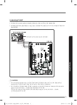
Diagram of connection between a FCU interface module and FCU KIT
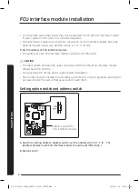
1
Fix the FCU interface module case at fixing point of FCU KIT by 1 screw.
2
Attach FCU interface module to the case and connect power and communication cable.
y
y
If you use upper level controller (such as DMS, OnOff controller, etc.) with the FCU
interface module installed, use of centralized control (02 series installation option - SEG5)
must be set as "Enable".
INSTALLATION
@FCU AIM-F10N_IM_06087A-00_EN_160307.indd 4
2016-03-15 오후 5:11:54
Содержание MIM-F10N
Страница 1: ...DB68 06087A 00 FCU AIM F10N_IM_06087A 00_EN_160307 indd 2 2016 03 15 오후 5 11 53 ...
Страница 11: ...10 INSTALLATION Memo FCU AIM F10N_IM_06087A 00_EN_160307 indd 10 2016 03 15 오후 5 11 54 ...
Страница 12: ...11 INSTALLATION FCU AIM F10N_IM_06087A 00_EN_160307 indd 11 2016 03 15 오후 5 11 54 ...