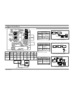
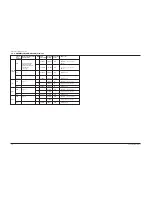
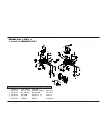
background image

Alignment and Adjustments

1-3

Samsung Electronics

(GND)

VTVM

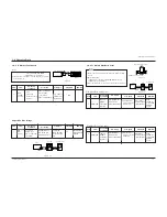
1-2-1 To Adjust Tape Speed

1) Measuring tape: i) MTT-111 (or equivalent)

(Tapes recorded with 3kHz)

ii) MTT-5512 (or equivalent)

2) Connect the cassette deck to the frequency  counter

as in figure 1-4.

1) Before the actual adjustment, clean the play/recording

head.

2) Measuring tape :

i) MTT-114(or equivalent 10kHz AZIMUTH control)

ii) MTT-112(or equivalent) :

3) The cassette deck is connections as shown in figure 1-6.

Notes

Notes

NOR 
SPEED
Control

1

OUT

(connected

to the frequency

counter)

Turn URV1 to
left and right

3KHz

Remark

Standard

To Adjust

Pre-Setup

Item

Step

Pre-Setup
Condition

1) Deck 1:MTT-111

2) Press PLAY 

SW button

3) Deck 2:MTT-5512

AZIMUTH

1

SPK OUT

(VTVM is 

connected to

the scope)

1) Turn the control 

screw to as shown
in Figure 1-5.

Max output
and same phase
(both channels)

After
adjustment
secure it with
REGION 
LOCK.

Remark

Standard

To Adjust

Pre-Setup

Item

Step

Pre-Setup
Condition

After putting MTT-

114 into Deck 1

1)Press PLAY button.

AZIMUTH

1

SPK OUT

(VTVM is 

connected to

the scope)

1) Turn the control 

screw to as shown
in Figure 1-5.

Max output
and same phase
(both channels)

After
adjustment
secure it with
REGION 
LOCK.

Remark

Standard

To Adjust

Pre-Setup

Item

Step

Pre-Setup
Condition

After putting MTT-

114 into Deck 2

1)Press  PLAY button.

1-2-2 To Adjust PlayBack Level

Adjust Deck 2 Play Level

Adjust Deck 1 Play Level

Cassette Deck

output

SPK OUT

Frequency Counter

Figure 1-4

Figure 1-5

SPK OUT

Recording /Play head

AZIMUTH control screw

Figure 1-6

In  Out

SET

Oscilloscope

1-2 Cassette Deck

REC
Bias
Voltage

1

Connect to

DCW2 as in

Fig.1-7 and read

the VTVM.

L-CH;DSR2
and R-CH;DSR1
to the right and
left.

6V

Remark

Standard

To Adjust

Pre-Setup

Item

Step

Pre-Setup
Condition

Input MTT-5512

into Deck2,then

press REC button.

See diagram
for adjustment
location

Adjust REC Bias Voltage

Figure 1-7 

SET

Oscilloscope

VTVM

IN

UCW2

FRONT PCB

Содержание MAX-VB630

Страница 1: ... COMPONENT MAX VB630 SERVICEManual MIMI MIMI COMPONENT SYSTEM CONTENTS 1 Alignment and Adjustments 2 Exploded Views and Parts List 3 Electrical Parts List 4 Block Diagrams 5 PCB Diagrams 6 Wiring Diagram 7 Schematic Diagrams ...

Страница 2: ...ntenna Terminal Distortion Meter Input SET Input output Oscilloscope FM IN FM Antenna SET 20 k OUTPUT AM SSG 450KHZ INPUT AM ANT IN Speaker Terminal 60cm AM IF VTVM Oscilloscope AM MW I F Adjustment Maximum output Figure 1 3 SSG FREQ Frequency Adjustment point 450 kHz 522 kHz AM IF Figure1 3 AM I F Adjustment OUTPUT Adjustment Location of Tuner PCB TESTER MAIN PCB VT GND Fig 1 4 OSC Voltage AM MW ...

Страница 3: ...1KHz MO Check for 7 0V 1 0V at the high Fig 1 3 IR117 AM MW RF 1 594KHz 594KHz MA Maximum out INTER FREQ 1 455KHz 522KHz AM IF Maximum out OSC Fig 1 3 1 146KHz LO Adjust for 2 0V 0 1V at the low LW 2 290KHz LO Check for 7 0V 1 0V at the high RF 1 150KHz 150KHz LA Maximum out OSC Fig 1 3 1 2 3MHz SO1 Adjust for 1 0V 0 1V at the low SW1 2 7 3MHz Check for 8 5V 1 0V at the high RF 1 3 5MHz 3 5MHz SA1...

Страница 4: ...stment secureitwith REGION LOCK Remark Standard To Adjust Pre Setup Item Step Pre Setup Condition AfterputtingMTT 114intoDeck1 1 PressPLAYbutton AZIMUTH 1 SPKOUT VTVMis connectedto thescope 1 Turnthecontrol screwtoasshown inFigure1 5 Maxoutput andsamephase bothchannels After adjustment secureitwith REGION LOCK Remark Standard To Adjust Pre Setup Item Step Pre Setup Condition AfterputtingMTT 114int...

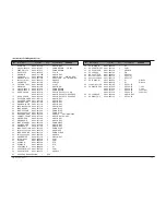
Страница 5: ...H81 00368A ASS Y RP HEAD ADR2400 RP SANKYO MT91 11010T 2 AH81 00141A HEAD PB TC881CB MT59 00044A 3 AH81 00363A ASS Y MOTOR ADR2400 SHU2L MT91 15012J 4 AH81 00364A BELT MAIN1 ADR2400 MAIN 0 5 6602 001056 5 AH81 00365A BELT MAIN2 ADR2400 MAIN 1 3 6602 001057 6 AH81 00101A BELT SUB ADR2400 FR 6602 001055 7 AH81 00102A SOLENOID ADR2400 1 MT75 00049A Samsung Electronics 2 1 ...

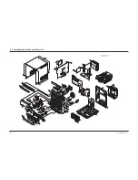
Страница 6: ...Samsung Electronics 2 2 2 2 Total Exploded View and Parts List ...

Страница 7: ...MPING 25 CABINET FRONT AH64 01700B 1 ABS L GRAYNO RDS 26 KNOB OPEN AH64 01709B 1 ABS L GRAY 27 KNOB DEMO AH64 01714B 1 ABS L GRAY 28 LENS STANDBY AH67 00159A 1 PMMA MILKY 29 KNOB POWER AH64 01708B 1 ABS L GRAY 30 KNOB ECHO AH64 01719B 1 ABS L GRAY 31 LENS FUNCTION AH67 00154C 1 PMMA BLUE 32 HOLDER FUNCTION AH61 00967A 1 ABS WHITE 33 LENS P SOUND AH67 00155A 1 PMMA CLEAR 34 HOLDER P SOUND AH61 0097...

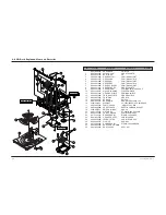
Страница 8: ...44 M0 5 PCD4 5 10 AH31 12001A MOTOR LOADING FF 030PN 09120 11 AH66 20193A GEAR ROULLETE POM M90 44 BLK 12 AH63 00324A TRAY ROULLETE ABS XR 401 BLK 13 AH63 00325A TRAY DISC ABS BLK 14 AH32 10001F SENSOR KPI L06 15 AH61 00837A BASE MAIN ABS NATURAL CMS 300 16 3302 000159 MAGNET AC 3500 3800G 2 6 3 2MGOe 30 17 AH63 90053A TABLE CHUCK ABS GF20 BLK 18 AH63 00068B SHEET CHUCK SHEET HYMERON BLK 0 4T 19 3...

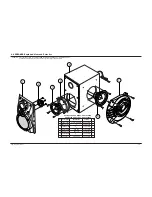
Страница 9: ... Specification PANEL P GRILLE 2 3 UNITWOOFER AH81 00642V 1 5 4 WOOFER RING AH81 00642G 1 HIPS BLK 5 CABINET ASS Y AH81 00642J 1 PB 9t 12t 6 UNIT SUBWOOFER AH81 00642U 1 6 7 SIDE PANEL AH81 00642E 1 HIPS WHITE PS VB630E ASS Y RIGHT AH81 00642X CAUSION It is used the bonding connet NET FRAME or FRONT PANEL ASS Y to CABINET ASS Y So when the disassembly take extreme care not to demage the SPEAKER ...

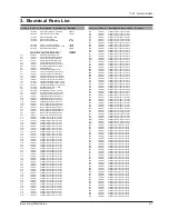
Страница 10: ...m 5 1 8W AA TP 1 8x3 2m R105 2001 000319 R CARBON 120Kohm 5 1 8W AA TP 1 8x3 2m MR53 2001 000325 R CARBON 120ohm 5 1 8W AA TP 1 8x3 2mm R117 2001 000331 R CARBON 12Kohm 5 1 8W AA TP 1 8x3 2mm R110 2001 000411 R CARBON 18Kohm 5 1 8W AA TP 1 8x3 2mm SR0 2001 000429 R CARBON 1Kohm 5 1 8W AA TP 1 8x3 2mm R806 2001 000429 R CARBON 1Kohm 5 1 8W AA TP 1 8x3 2mm R805 2001 000429 R CARBON 1Kohm 5 1 8W AA T...

Страница 11: ...C AXIAL 10NF 30 16V Y5S TP C204 2202 000797 C CERAMIC MLC AXIAL 10NF 30 16V Y5S TP C209 2202 000797 C CERAMIC MLC AXIAL 10NF 30 16V Y5S TP C213 2202 000797 C CERAMIC MLC AXIAL 10NF 30 16V Y5S TP C127 2202 000806 C CERAMIC MLC AXIAL 220pF 10 50V Y5P TP C125 2202 000814 C CERAMIC MLC AXIAL 390pF 10 50V Y5P TP MC13 2202 000825 C CERAMIC MLC AXIAL 680pF 10 50V Y5P TP C203 2202 000829 C CERAMIC MLC AXI...

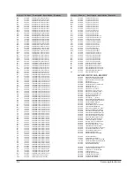
Страница 12: ... 5 1 8W AA TP 1 8x3 2mm UR42 2001 000290 R CARBON 10Kohm 5 1 8W AA TP 1 8x3 2mm UR27 2001 000290 R CARBON 10Kohm 5 1 8W AA TP 1 8x3 2mm UR28 2001 000290 R CARBON 10Kohm 5 1 8W AA TP 1 8x3 2mm UR3 2001 000290 R CARBON 10Kohm 5 1 8W AA TP 1 8x3 2mm UR39 2001 000290 R CARBON 10Kohm 5 1 8W AA TP 1 8x3 2mm UR4 2001 000290 R CARBON 10Kohm 5 1 8W AA TP 1 8x3 2mm UR40 2001 000290 R CARBON 10Kohm 5 1 8W AA...

Страница 13: ...003755 C AL 6800UF 20 35V BP TP 22X40MM 1 RC3 2401 003755 C AL 6800UF 20 35V BP TP 22X40MM 1 RSW1 3408 000177 SWITCH SLIDE 250V 5A DPDT ON OFF OPTION RRL1 3501 001008 RELAY POWER 12Vdc 530mW 10A 1FormC 15mS RF2 3601 000248 FUSE CARTRIDGE 250V 2A TIME LAG GLASS 5x RF1 3601 000282 FUSE 250V 4A TIME LAG GLASS 5 2x20m TCW1 3708 000122 CONNECTOR FPC FFC PIC 11P 1 25mm ANGLE S FCW4 3708 000181 CONNECTOR...

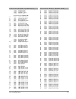
Страница 14: ... CARBON 470Kohm 5 1 8W AA TP 1 8x3 2m FR23 2001 000773 R CARBON 470Kohm 5 1 8W AA TP 1 8x3 2m WR50 2001 000780 R CARBON 470ohm 5 1 8W AA TP 1 8x3 2mm RR22 2001 000786 R CARBON 47Kohm 5 1 8W AA TP 1 8x3 2mm RR20 2001 000786 R CARBON 47Kohm 5 1 8W AA TP 1 8x3 2mm KR17 2001 000786 R CARBON 47Kohm 5 1 8W AA TP 1 8x3 2mm VR15 2001 000786 R CARBON 47Kohm 5 1 8W AA TP 1 8x3 2mm VR4 2001 000786 R CARBON 4...

Страница 15: ... 2009 001117 R METAL PLATE 0 1OHM 5 5W CL BK 5X13X18 PR59 2009 001117 R METAL PLATE 0 1OHM 5 5W CL BK 5X13X18 PR47 2009 001117 R METAL PLATE 0 1OHM 5 5W CL BK 5X13X18 PR46 2009 001117 R METAL PLATE 0 1OHM 5 5W CL BK 5X13X18 PR45 2009 001117 R METAL PLATE 0 1OHM 5 5W CL BK 5X13X18 PC22 2401 000230 C AL 100uF 20 100V GP TP 12 5x20mm PC23 2401 000230 C AL 100uF 20 100V GP TP 12 5x20mm PC24 2401 00023...

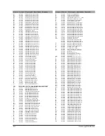
Страница 16: ...1W AA TP 3 3 PR9 2003 000689 R METAL OXIDE S 4 7ohm 5 1W AA TP 3 3x PR8 2003 000689 R METAL OXIDE S 4 7ohm 5 1W AA TP 3 3x PR7 2003 000689 R METAL OXIDE S 4 7ohm 5 1W AA TP 3 3x PR38 2003 000689 R METAL OXIDE S 4 7ohm 5 1W AA TP 3 3x PR10 2003 000689 R METAL OXIDE S 4 7ohm 5 1W AA TP 3 3x PC13 2201 000300 C CERAMIC DISC 1nF 20 50V Y5T TP 5x3 5 PC12 2201 000300 C CERAMIC DISC 1nF 20 50V Y5T TP 5x3 ...

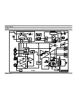
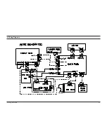
Страница 17: ...Samsung Electronics 1 4 Block Diagram 4 1 MAIN ...

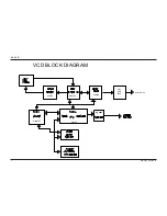
Страница 18: ...2 Samsung Electronics 4 2 VCD 1 2 KA9259 KB9226 KS9290 AIC3 AMP 4558 AUDIO OUT M66Q587 W9923 VCD BLOCK DIAGRAM ...

Страница 19: ...Samsung Electronics 6 1 6 Wiring Diagram ...

Страница 20: ...Samsung Electronics 7 1 7 Schematic Diagram 7 1 VCD MPEG MICOM ...

Страница 21: ...7 2 Samsung Electronics 7 2 VCD SERVO ...

Страница 22: ...Samsung Electronics 7 3 7 3 MAIN ...

Страница 23: ...7 4 Samsung Electronics 7 4 FRONT ...

Страница 24: ...Samsung Electronics 7 5 7 5 AMP ...

Страница 25: ...7 6 Samsung Electronics 7 6 TUNER EURO ...

Страница 26: ...Samsung Electronics 7 7 7 7 TUNER RUSIA ...

Страница 27: ...7 8 Samsung Electronics 7 8 TUNER 2BAND ...

Страница 28: ... Samsung Electronics Co Ltd SEP 2002 Printed in Korea Code no AH68 01168Z ...

Отзывы: