background image

5-4

Samsung Electronics

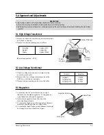
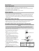
1) Pour 275

¡

15cc of 20

¡

5

¡

( 68

¡

9

¢

) water in a

beaker which is graduated to 600cc, and place
the beaker in the center of the oven.

2) Start to operate the oven and measure the

leakage by using a microwave energy survey
meter.

3) Set survey meter with dual ranges to 2,450MHz.
4) When measuring the leakage, always use the 2

inch spacer cone with the probe. Hold the probe
perpendicular to the cabinet door. Place the
spacer cone of the probe on the door and/or
cabinet door seam and move along the seam, the
door viewing window and the exhaust openings
moving the probe in a clockwise direction at a rate of 1 inch/sec. If the leakage testing of the cabinet door
seam is taken near a corner of the door, keep the probe perpendicular to the areas making sure that the
probe end at the base of the cone does not get closer than 2 inches to any metal. If it gets closer than 2
inches, erroneous readings may result.

5) Measured leakage must be less than 4mW/cm

2

, after repair or adjustment.

Alignment and Adjustments

5-13 Leakage Measuring Procedure

5-10 Procedure for  Measurement of Microwave Energy Leakage

5-12 Note on Measurement

5-11 Check for Microwave Leakage 

5-13-1 Record keeping and notification after measurement

1) After adjustment and repair of a radiarion preventing device, make a repair record for the measured

values, and keep the data.

2) If the radiation leakage is more than 4 mW/

§†

after determining that all parts are in good condition,

functioning properly and the identical parts are replaced as listed in this manual notift that fact to ;

CENTRAL SERVICE CENTER

5-13-2 At least once a year have the microwave energy survey meter checked for accuracy by its

manufacturer.

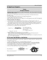
1.  Remove the outer panel. 
2.  Pour 275±15cc of 20±5ûC(68±9ûF) water in a

beaker which is graduated to 600cc, and
place the beaker   in the center of the oven.

3.  Start the oven at the highest power level.
4.  Set survey meter dual ranges to 2,450MHz.
5. Using the survey meter and spacer cone as

described above, measure  arnear the
opening of magnetron, the surface of the air
guide and the surface of the wave guide as
shown in the following photo.( but avoid the
high voltage components.)  The neading
should be less than 4mW/cm

2

.

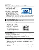
1) Do not exceed the limited scale.
2) The test probe must be held on the grip of the handle, otherwise a false reading may result when the

operator's hand is between the handle and the probe.

3) When high leakage is suspected, do not move the probe horizontally along the oven surface; this may

cause damage to the probe.

4) Follow the recommendation of the manufacturer of the microwave energy survey meter.

Maximum allowable leakage is 5mW/cm

2

.

4mW/cm

2

is used to allow for measurement and meter accuracy

Содержание M643

Страница 1: ...anual MICROWAVE OVEN CONTENTS 1 Precaution 2 Specifications 3 Operating Instructions 4 Disassembly and Reassembly 5 Alignment and Adjustments 6 Troubleshooting 7 Exploded Views and Parts List 8 PCB Diagrams 9 Schematic Diagrams NSI ...

Страница 2: ...k switches interlock monitor switch 12 If the fuse is blown by the Interlock Monitor Switch Replace all of the following at the same time Primary and secondary switches as well as the Interlock Monitor Switch The correct adjustment of these switches is described elsewhere in this manual Make sure that the fuse has the correct rating for the particular model being repaired 13 Design Alteration Warn...

Страница 3: ...es this includes the filament voltage of the magnetron High voltage is present during any cook cycle Before touching any components or wiring always unplug the oven and discharge the high voltage capacitor See Figure 1 1 2 The high voltage capacitor remains charged about 30 seconds after disconnection Short the negative terminal of the high voltage capacitor to to the oven chassis Use a screwdrive...

Страница 4: ...G METHOD COOLING FAN MOTOR OUTSIDE DIMENSIONS 489 W x 275 H x 351 D POWER LEVEL M643 10 75W 4 sec 26 sec 20 150W 7 sec 23 sec 30 225W 10 sec 20 sec 40 300W 13 sec 17 sec 50 375W 16 sec 14 sec 60 450W 19 sec 11 sec 70 525W 22 sec 8 sec 80 600W 25 sec 5 sec 90 675W 28 sec 2 sec 100 750W 30 sec 0 sec ON TIME OFF TIME 2 2 Comparison Chart MODEL FEATURE MORE LESS AUTO COOK DISH AUTO DEFROST O TIME COOK...

Страница 5: ...wer Level Selection Button Auto 0 1 kg 1min 3 Operating Instructions 3 1 Control Panel Samsung Electronics 3 1 3 2 Features External Views Door VentilationSlot Light SafetyInterlockHoles ControlPanel OpenDoorPushButton GuideRoller GlassPlate DoorLatches 10min 1min h 10s min M643 Auto 0 1 kg 1min 489mm 357mm 275mm 200mm 351mm 10min 1min h 10s min M643 Auto 0 1 kg 1min ...

Страница 6: ...gnetron very carefully 7 Remove screws from the back panel 8 Take out the fan motor 9 Remove the oven lamp by rotating to pull out from hole of air cover NOTE1 When removing the magnetron make sure that its antenna does not hit any adjacent parts or it may be damaged NOTE2 When replacing the magnetron be sure to remount the magnetron gasket in the correct position and make sure the gasket is in go...

Страница 7: ...ndling Door C because it is fragile Following the procedure as shown in the figure insert and bend a thin metal plate between Door E and Door A until you hear the tick sound 1 Insertion depth of the thin metal plate should be 0 5mm or less Remove pin hinge from Door E Detach spring from Door E and key door 4 3 2 Removal of Door C 4 3 3 Removal of Door E Disassembly and Reassembly Upper Hinge Lower...

Страница 8: ...hen replacing the drive motor be sure to remount it in the correct position 8 Connect all the leads to the drive motor 9 Screw the deive motor cover to the base plate with a screw driver 10 Remount the coupler in the correct position 4 4 Replacement of Fuse 4 5 Replacement of Drive Motor Disassembly and Reassembly Screw Drive Motor Cover Base Plate Drive Motor After replacement of the defective co...

Страница 9: ...onnecting the FPC connector make sure that the holes on the connector are properly engaged with the hooks on the Plastic Fastener 1 Window display should not be disassembled as its mounting tabs will be broken If repair work is difficult replace with Ass y control panel 2 The membrane key board is attached to the escutcheon base with doublefaced adhesive tape Therefore applying hot air such as usi...

Страница 10: ...nt terminal and magnetron case should read open 1 The low voltage transformer is located on the control circuit board 2 Remove the low voltage transformer from the PCB Ass y and check continuity 3 Normal resistor reading is shown in the table PRECAUTION 1 High voltage is present at the high voltage terminals during any cook cycle 2 It is neither necessary nor advisable to attempt measurement of th...

Страница 11: ...just the Latch Body by moving it so that the oven door will not have any play in it Check for play in the door by pulling the door assembly Make sure that the latch keys move smoothly after adjustment is completed Completely tighten the screws holding the Latch Body to the oven assembly 4 Reconnect to Monitor switch and check the continuity of the monitor circuit and all latch switches again by fo...

Страница 12: ...nal power test should be made if temperature rise is marginal NOTE 2 Output power in watts is computed by multiplying the temperature rise step E by a factor of 91 times the of centigrade temperature The microwave heat distribution can be checked indirectly by measuring the water temperature rise at certain positions in the oven 1 Prepare five beakers made of Pyrex having 100 milliliters capacity ...

Страница 13: ...repair of a radiarion preventing device make a repair record for the measured values and keep the data 2 If the radiation leakage is more than 4 mW after determining that all parts are in good condition functioning properly and the identical parts are replaced as listed in this manual notift that fact to CENTRAL SERVICE CENTER 5 13 2 At least once a year have the microwave energy survey meter chec...

Страница 14: ...witch 3 Defective monitor switch NOTE1 4 Shorted HVCapacitor 5 Shorted HVTransformer NOTE2 NOTE 1 All of these switches must be replaced at the same time refer to adjustment instructions Check continuity of power relay contacts and if it has continuity replace power relay also NOTE 2 When HVTransformer is replaced check diode and magnetron also Oven does not accept 1 Key input is not in Sequence R...

Страница 15: ...noise can be heard 1 Loose fan and fan motor Tighten screws of fan motor 2 Loose screws on H V Transformer Tighten screws of H V Transformer 3 Shorted H V Diode Replace H V Diode Turntable motor does not rotate 1 Open or loose wiring of turntable motor Replace turntable motor 2 Defective turntable motor Oven stops operation during cooking 1 Open or loose wiring of primary Adjust door and latch swi...

Страница 16: ...Exploded Views and Parts List 7 1 Exploded Views 7 1 M 1 M4 M3 M5 M9 M8 M11 M20 M21 M23 M25 M26 M18 M17 M16 M27 M28 M29 M32 D1 M30 M6 M7 M10 M2 M12 M13 M15 M12 M14 M22 M24 M19 M31 C1 C2 C3 C4 C5 C6 D5 D6 D4 D7 D8 D2 D9 D3 C7 ...

Страница 17: ...DY POM F20 02 40GR NTR 1 M 16 DE74 20102B TRAY COOKING GLASS T5 0 PI288 780G M745 1 M 17 DE92 90436A ASSY GUIDE ROLLER MW4370W 1 M 18 DE67 60002A COUPLER PPS 5GR BRN M97G45 1 M 19 DE27 10020A COIL MC CHOKE TC 101 1 M 20 2501 001036 C OIL 950nF 2100V BK 35x54x85 20mm 1 M 21 DE61 50106A BRACKET HVC SECC T0 8 W31 L125 8 1 M 22 DE91 70063A ASSY HVD V2M6 PI9 0 0 05MT 1 M 23 DE91 70061B ASSY H V FUSE TH...

Страница 18: ...List 7 4 Control Parts List 7 3 Door Parts List Parts No Description Specification Q ty Remarks DE60 10098A SCREW ASSY TAPTITE PH TC M4X8 SWRCH18A Z 2 MO DRI DE60 10088A SCREW TAP PH PH M3 L8 FEFZY PLAIN 2 PCB DE60 10098A SCREW ASSY TAPTITE PH TC M4X8 SWRCH18A Z 1 HVD DE60 10082H SCREW A 2S 4X12 TOOTHED 2 CON BX DE60 10012A SCREW TAP TITE TH 3 M4 L10 SWR10 ZPC2 1 MEM PN DE60 10098A SCREW ASSY TAPT...

Страница 19: ...8 P C B Diagrams 8 1 P C B Diagrams Samsung Electronics 8 1 ...

Страница 20: ...0273 R CARBON 100Kohm 5 1 8W AA TP 1 8x3 2m 1 R19 2001 000290 R CARBON 10Kohm 5 1 8W AA TP 1 8x3 2mm 11 R07 R11 R14 R16 R17 R23 R25 2001 000429 R CARBON 1Kohm 5 1 8W AA TP 1 8x3 2mm 6 R04 R05 R06 R12 R15 R22 2001 000446 R CARBON 2 2Kohm 5 1 2W AA TP 3 3x9mm 2 R03R33 2001 000613 R CARBON 3 9Kohm 5 1 8W AA TP 1 8x3 2m 3 R13R18R20 2001 000841 R CARBON 51ohm 5 1 4W AA TP 2 4x6 4mm 7 R26 R32 2001 00090...

Страница 21: ...Y MAIN RELAY F FA MAGNETRON NO COM NO NO BLU YEL BRN BRN BRN BLK BLU BLK COM 0V LAMP 230V40W L V TRANS PRIMARY LATCH SWITCH NO COM ORG ORG MONITOR SWITCH L FM H V T H V D H V C H V FUSE 1mH BRN BROWN BLU BLUE ORG ORANGE RED RED WHT WHITE BLK BLACK YEL YELLOW GRN GREEN Y G YELLOW GREEN SYMBOL COLOR NOTE MAIN FUSE DM 1 INPUT 230V 2 DOOR OPEN 3 LAMP ON 4 P C B PATTERN 5 P C B IN OUT POINT ASSY MAIN P...

Отзывы: