background image


English     32


Appendix


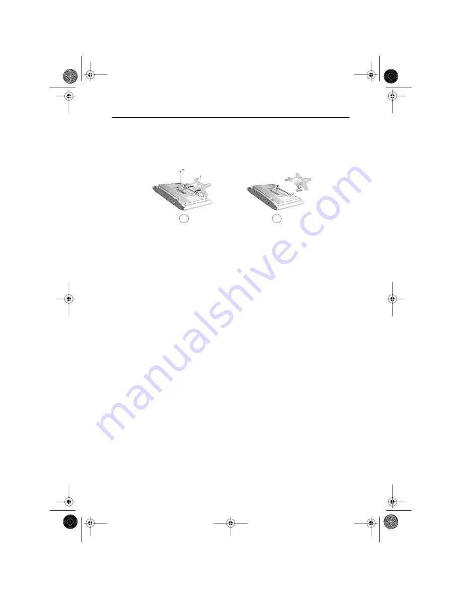
Attaching a wall or Arm mounting device


The TV/Monitor supports VESA mounting standard for use with various VESA mounting 
devices.  To install any VESA mounting device, please follow the instructions given.


1


Lay the LCD TV/Monitor face-down on a flat surface with a cushion or other soft 
materials to protect the screen.


2


Remove all cable connected on the TV/Monitor.


3


Remove the four screws and then remove the Stand from the LCD TV/Monitor.
(refer to the picture A&B)


4


Connect all cable you removed at step 2.


5


Now you are ready to install Wall/Arm mounting device depending on your 
applications.

B

A

6E_body17p.fm  Page 32  Wednesday, December 19, 2001  4:50 PM

Содержание LW-17E24C

Страница 1: ...LW 15E23C LW 17E24C For PAL systems TFT LCD TV Monitor User s Manual 1E_cov fm Page 1 Wednesday January 23 2002 9 02 AM...

Страница 2: ...splay screen that is appeared as window termination button is pressed If there s still noise after automatic adjustment use FINE COARSE adjustment function Manufactured under license from Dolby Labora...

Страница 3: ...0 OSD Lock Unlock 10 On Screen Display OSD 11 Accessing the Menu System 11 OSD Functions and Adjustments 12 PC Functions and Adjustments 13 TV Video Functions and Adjustments 17 Appendix 20 By Remote...

Страница 4: ...rain or use it near water in kitchens near swimming pools etc If the LCD TV Monitor accidentally gets wet unplug it and contact an authorized dealer immediately You can clean the LCD TV Monitor with...

Страница 5: ...ssing contact your dealer Manual Warranty Card Not available in all locations Installation CD Not available in all locations DC Adapter Power Cord TV Monitor 15 pin D Sub Signal Cable Remote Controlle...

Страница 6: ...on from lights or windows usually at a right angle to any window Workstation height Place your LCD TV Monitor so that the top of the screen is slightly below your eye level when you are comfortably se...

Страница 7: ...Driver section on page 6 2 Connecting External A V Devices A Connect RCA audio cables to Audio R and Audio L terminals and the other ends to corresponding audio out terminals on the A V device Stereo...

Страница 8: ...stalling the Video Driver The CD that accompanies this product contains the necessary drivers for installing your TV Monitor Please refer to the driver installation instructions included with your CD...

Страница 9: ...ystem your TV Monitor is functioning properly Getting Help If your TV Monitor does not display an image check your cable connections and refer to Troubleshooting on page 25 If you experience difficult...

Страница 10: ...5 User control locations No Name Description 1 PC Selects PC source PIP window off 2 PIP Activates PIP Picture in Picture window directly in PC mode Selects video sources in PIP TV Video1 scart Video...

Страница 11: ...n page 31 If you have made no adjustments the OSD disappears and the TV Monitor does not save anything 7 VOL Moves the selector left or right on the OSD Increases or decreases the values of the select...

Страница 12: ...Exit Auto 4 Remote Controller All direct access keys on the remote controller Initial OSD icons Some OSD menus are disabled in gray color when they are not available in a certain mode of operation Th...

Страница 13: ...n once to activate the highlighted function then follow the Tool Tips to select the function and adjust the value 4 Use and buttons to select the sub menu and press the MENU button once to activate th...

Страница 14: ...e vertical and horizontal direction Halftone Change the opaqueness of the background of the OSD Duration The number of seconds that the OSD will remain visible before disappearing Size Melody Resize t...

Страница 15: ...n be changed from redish white to bluish white The individual color components are also user customizable Mode1 Reddish white Mode2 Plain white Mode3 Bluish white User Mode User customizable Reset Col...

Страница 16: ...ny noise If satisfactory results are not obtained using the Fine adjustment use the Coarse adjustment and then use Fine again This function may change the width of the image Use the H Position menu to...

Страница 17: ...ay the incoming image as it is applicable to PC RGB only Zoom The image can be magnified up to 64 times larger than the original image The enlarged image can also be panned Pan Move the zoomed image h...

Страница 18: ...igh frequency audio Virtual Dolby Surround On Off PIP Picture in Picture When external A V devices such as VCR DVD or RF TV cable are connected to the TV Monitor PIP allows you to watch video from suc...

Страница 19: ...s contrast Applicable to Custom mode only Brightness Adjust the brightness of video or TV without affecting PC RGB s brightness Applicable to Custom mode only Sharpness Adjust the sharpness of video...

Страница 20: ...the channels found automatically The following Countries are available Belgie Deutschland Espania France Italia Nederland Schweiz Sverige UK East Europe Manual Store Color system Adjust repeatedly unt...

Страница 21: ...or button Fine Tune To select the Fine tune and press the or button Channel Sort Channel order can be re arranged by this menu Active Area Normal 16 9 Timer The TV Monitor system will turn off automa...

Страница 22: ...rect channel access Previous channel Self adjust to the incoming video signal PIP On PIP source change Sound mute TV Video mode on Source Change Thediversescreen users need PC mode On Display setup in...

Страница 23: ...mode is displayed on the upper right corner of the screen Note LW 15E23C 17E24C have an automatic stereo detection feature Thus depending on the types of audio the TV Monitor automatically changes th...

Страница 24: ...is key is used to cross out the TTX display completely on the screen TTX is still valid under CANCEL when the key is inserted P 9 L 200 300 400 899 P 200 VGB 08 40 21 VGB Broadcast P 200 VGB 08 40 21...

Страница 25: ...s valid INDEX FLOF moves to the INDEX and TOP moves to INFO in the time of inputting this key LIST FLOF It has converted to the LIST MODE and FLOF MODE FLOF MODE is released and then transferred to LI...

Страница 26: ...his TV Monitor automatically returns to normal operation when horizontal and vertical sync return This occurs when you move the computer s mouse or press a key on the keyboard This TV Monitor is EPA E...

Страница 27: ...PC or video sources Ensure that the PC or video sources are turned on Connecting your LCD TV Monitor page 5 Sync Out of Range message Check the maximum resolution and the frequency of the video adapto...

Страница 28: ...hange the display settings Installing the Video Driver page 6 NOTE Your TV Monitor supports multiscan display functions within the following frequency domain Horizontal frequency Vertical frequency Ma...

Страница 29: ...Check the volume level Sound Controls Sound level is too low Check the volume level Sound Controls If the volume is still too low after turning the control to its maximum check the volume control on t...

Страница 30: ...ical Display color 30 69 kHz 56 85 Hz 16 777 216 colors 30 81 kHz 56 85 Hz XGA 60 76 Hz SXGA 16 777 216 colors Display Resolution Optimum Mode Maximum Mode 1024 x 768 60 Hz 1024 x 768 85 Hz 1280 x 102...

Страница 31: ...10 5 lbs 530 x 447 x 204 mm 4 8 kg Environmental Considerations Operating Temperature Operating Humidity Storage Temperature Storage Humidity 50 F to 104 F 10 C to 40 C 10 to 80 13 F to 113 F 25 C to...

Страница 32: ...ND DDC Return GND DDC Return 6 GND Red GND Red GND Red 7 GND Green GND Green GND Green 8 GND Blue GND Blue GND Blue 9 No Connection No Connection Not used 10 GND Sync Self Test GND Sync Self Test GND...

Страница 33: ...ring manufacture Table 7 Preset timing modes Mode Resolution Horizontal Frequency kHz Vertical Frequency Hz Pixel Clock Frequency MHz Sync Polarity H V VGA 720 x 400 31 469 70 087 28 322 640 x 480 31...

Страница 34: ...TV Monitor face down on a flat surface with a cushion or other soft materials to protect the screen 2 Remove all cable connected on the TV Monitor 3 Remove the four screws and then remove the Stand fr...

Страница 35: ...C 15 No 47 007 099 Pivot direct mount adapter No 97 101 003 Wall mount bracket kit LW 17E24C 17 No 47 007 099 02 Pivot direct mount adapter No 97 101 003 00 Wall mount bracket kit Align the wall mount...

Страница 36: ...to the cable connectors as described on page 5 Users cannot service the TV Monitor User maintenance is restricted to cleaning as explained below Unplug the TV Monitor from the power outlet before clea...

Страница 37: ...2 M Manual Store 18 Melody 12 MENU 8 Mode 13 17 18 MUTE 8 O On Screen Display 11 OSD Lock Unlock 10 P Pan 15 PC 8 Picture 17 Pin Assignments 30 PIP 8 16 PIP Position 16 PIP Size 16 Plug and Play 6 Pos...

Страница 38: ...oducts Marked with FCC Logo This device complies with Part 15 of the FCC Rules Operation is subject to the following two conditions 1 this device may not cause harmful interference and 2 this device m...

Страница 39: ...n Surrey KT6 7LD Tel 0208 391 0168 Fax 0208 397 9949 European Service Center National Service Stafford Park 12 Telford Shropshire TF3 3BJ Tel 0870 242 0303 Fax 01952 292 033 http samsungservice co uk...

Отзывы: