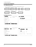
4-3-1 Conditions for Measurement
1. On the basis of toshiba ABL pattern : High Light level (57 IRE)
- INPUT SIGNAL GENERATOR : MSPG-925LTH
2. Optical measuring device : CA210 (FL)
4-3-2 Method of Adjustment
1. Adjust the basic level of DTV and PC input signals.
a) Set the input to the mode in which the adjustment will be made (DTV
PC).
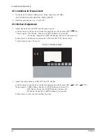
* Input signal - DTV Mode : Model #6 (1280*720 Mode), Pattern #36
- PC Mode : Model #21 (1024*768 Mode), Pattern #16 (Picture 4-1)
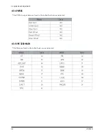
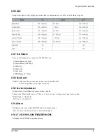
b) Enter factory Calibration, confirm the ADC data (DTV, PC Mode Only).
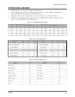
* ADC default value : Table 4-3.
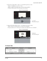
2. Adjust the white balance of RF, DTV and PC Modes.
a) Set the input to the mode in which the adjustment will be made (RF
DTV PC).
* Input signal - VIDEO Mode : Model #1 (750*480 Mode), Pattern #16
- DTV Mode : Model #6 (1280*720 Mode), Pattern #16
- PC Mode : Model #21 (1024*768 Mode), Pattern #16
b) Enter factory color control, confirm the data.
4 Alignments and Adjustments
4-6
LT17N23W
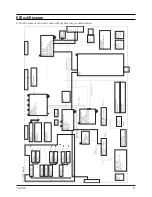
Picture 4-1 Toshiba ABL Pattern
Содержание LT17N23W
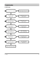
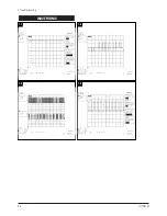
Страница 4: ...5 Troubleshooting 5 2 LT17N23W WAVEFORMS 1 1 1 2 1 3 1 4...
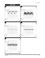
Страница 5: ...WAVEFORMS 1 5 1 6 1 7 5 Troubleshooting LT17N23W 5 3...
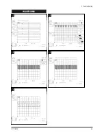
Страница 7: ...5 Troubleshooting LT17N23W 5 5 WAVEFORMS 2 1 2 2 2 3 2 5 2 4...
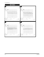
Страница 9: ...5 Troubleshooting LT17N23W 5 7 WAVEFORMS 3 1 3 2 3 3 3 4 3 5...
Страница 10: ...5 Troubleshooting 5 8 LT17N23W WAVEFORMS 3 6 3 7 3 8 3 9...
Страница 14: ...4 Alignments and Adjustments LT17N23W 4 3...
Страница 15: ...4 Alignments and Adjustments 4 4 LT17N23W...
Страница 21: ...8 Block Diagram This Document can not be used without Samsung s authorization LT17N23W 8 1...

