4-42
4. Troubleshooting
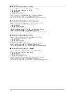
Method of Color Calibration (AV)
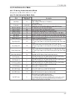
1) Apply the NTSC Lattice (N0. 3) pattern signal to the AV IN 1 port
2) Press the Source key to switch to “AV1” mode
3) Enter Service mode
4) Select the “Calibration” menu
5) Select the “AV Calibration” menu.
6) In “AV Calibration Off” status, press the “ ” key to perform Calibration.
7) When Calibration is complete, it returns to the high-level menu.
8) You can see the change of the “AV Calibration” status from Failure to Success.
Method of Color Calibration (Component)
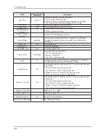
1) Apply the 720p Lattice (N0. 6) pattern signal to the Component IN 1 port
2) Press the Source key to switch to “Component1” mode
3) Enter Service mode
4) Select the “Calibration” menu
5) Select the “Comp Calibration” menu.
6) In “Comp Calibration Off” status, press the “ ” key to perform Calibration.
7) When Calibration is complete, it returns to the high-level menu.
8) You can see the change of the “Comp Calibration” status from Failure to Success.
Method of Color Calibration (PC)
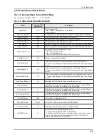
1) Apply the VESA XGA Lattice (N0. 21) pattern signal to the PC IN port
2) Press the Source key to switch to “PC” mode
3) Enter Service mode
4) Select the “Calibration” menu
5) Select the “PC Calibration” menu.
6) In “PC Calibration Off” status, press the “ ” key to perform Calibration.
7) When Calibration is complete, it returns to the high-level menu.
8) You can see the change of the “PC Calibration” status from Failure to Success.
Method of Color Calibration (HDMI)
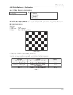
1) Apply the 720p Lattice (N0. 6) pattern signal to the HDMI1/DVI IN port
2) Press the Source key to switch to “HDMI1” mode
3) Enter Service mode
4) Select the “Calibration” menu
5) Select the “HDMI Calibration” menu.
6) In “HDMI Calibration Off” status, press the “ ” key to perform Calibration.
7) When Calibration is complete, it returns to the high-level menu.
8) You can see the change of the “HDMI Calibration” status from Failure to Success.
Содержание LN40B550K1H
Страница 62: ...4 3 4 Troubleshooting L1 B13V B5V B12V B5V 1 9V B3 3V B9V ...
Страница 64: ...4 5 4 Troubleshooting Pin 16 17 Pin 34 35 TP67 TP69 TP71 TP72 TP70 ...
Страница 65: ...4 6 4 Troubleshooting WAVEFORMS 1 PC input V sink H sink R G B 2 LVDS output ...
Страница 67: ...4 8 4 Troubleshooting Pin 16 17 Pin 34 35 Pin 12 Pin 7 ...
Страница 68: ...4 9 4 Troubleshooting WAVEFORMS 3 HDMI input RX_Data RX_Clk 2 LVDS output ...
Страница 70: ...4 11 4 Troubleshooting Pin 16 Pin 17 Pin 2 Pin 4 Pin 8 ...
Страница 71: ...4 12 4 Troubleshooting WAVEFORMS 4 CVBS OUT Grey Bar 2 LVDS output ...
Страница 73: ...4 14 4 Troubleshooting Pin 16 17 Pin 34 35 Pin 2 Pin 4 ...
Страница 74: ...4 15 4 Troubleshooting WAVEFORMS 2 LVDS output ...
Страница 76: ...4 17 4 Troubleshooting Pin 16 17 Pin 34 35 V3CVBS COMY ...
Страница 77: ...4 18 4 Troubleshooting WAVEFORMS 4 CVBS OUT Grey Bar 2 LVDS output ...
Страница 79: ...4 20 4 Troubleshooting Pin 16 17 Pin 34 35 COMY COMPB COMPC ...
Страница 80: ...4 21 4 Troubleshooting WAVEFORMS 5 Compnent_Y Gray scale Pb Pr Color bar 2 LVDS output ...
Страница 82: ...4 23 4 Troubleshooting R416 B12V COMSL COMSR V2SR V2SL TP_L L R R DSL DSR TP_915 TP_916 B3 3V ...
Страница 83: ...4 24 4 Troubleshooting WAVEFORMS 6 I2C Data 7 Speaker out ...
Страница 119: ...6 6 6 Wiring Diagram Memo ...


