INTERRUPTS
KS57C2308/P2308/C2316/P2316
7-2
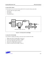
Vectored Interrupts
Interrupt requests may be processed as vectored interrupts in hardware, or they can be generated by program
software. A vectored interrupt is generated when the following flags and register settings, corresponding to the
specific interrupt (INTn) are set to logic one:
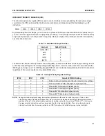
— Interrupt enable flag (IEx)
— Interrupt master enable flag (IME)
— Interrupt request flag (IRQx)
— Interrupt status flags (IS0, IS1)
— Interrupt priority register (IPR)
If all conditions are satisfied for the execution of a requested service routine, the start address of the interrupt is
loaded into the program counter and the program starts executing the service routine from this address.
EMB and ERB flags for RAM memory banks and registers are stored in the vector address area of the ROM
during interrupt service routines. The flags are stored at the beginning of the program with the VENT instruction.
The initial flag values determine the vectors for resets and interrupts. Enable flag values are saved during the
main routine, as well as during service routines. Any changes that are made to enable flag values during a
service routine are not stored in the vector address.
When an interrupt occurs, the EMB and ERB flag values before the interrupt is initiated are saved along with the
program status word (PSW), and the enable flag values for the interrupt is fetched from the respective vector
address. Then, if necessary, you can modify the enable flags during the interrupt service routine. When the
interrupt service routine is returned to the main routine by the IRET instruction, the original values saved in the
stack are restored and the main program continues program execution with these values.
Software-Generated Interrupts
To generate an interrupt request from software, the program manipulates the appropriate IRQx flag. When the
interrupt request flag value is set, it is retained until all other conditions for the vectored interrupt have been met,
and the service routine can be initiated.
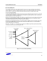
Multiple Interrupts
By manipulating the two interrupt status flags (IS0 and IS1), you can control service routine initialization and
thereby process multiple interrupts simultaneously.
If more than four interrupts are being processed at one time, you can avoid possible loss of working register data
by using the PUSH RR instruction to save register contents to the stack before the service routines are executed
in the same register bank. When the routines have executed successfully, you can restore the register contents
from the stack to working memory using the POP instruction.
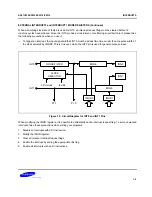
Power-Down Mode Release
An interrupt (with the exception of INT0) can be used to release power-down mode (stop or idle). Interrupts for
power-down mode release are initiated by setting the corresponding interrupt enable flag. Even if the IME flag is
cleared to zero, power-down mode will be released by an interrupt request signal when the interrupt enable flag
has been set. In such cases, the interrupt routine will not be executed since IME = "0".
Содержание KS57C2308
Страница 30: ...ADDRESS SPACES KS57C2308 P2308 C2316 P2316 2 22 NOTES ...
Страница 168: ...SAM47 INSTRUCTION SET KS57C2308 P2308 C2316 P2316 5 94 NOTES ...
Страница 170: ......
Страница 206: ...POWER DOWN KS57C2308 P2308 C2316 P2316 8 8 NOTES ...
Страница 210: ...RESET KS57C2308 P2308 C2316 P2316 9 4 NOTES ...
Страница 222: ...I O PORTS KS57C2308 P2308 C2316 P2316 10 12 NOTES ...
Страница 272: ...LCD CONTROLLER DRIVER KS57C2308 P2308 C2316 P2316 12 24 NOTES ...
Страница 280: ...SERIAL I O INTERFACE KS57C2308 P2308 C2316 P2316 13 8 NOTES ...
Страница 294: ...MECHANICAL DATA KS57C2308 P2308 C2316 P2316 15 2 NOTES ...
Страница 310: ...KS57P2308 P2316 OTP KS57C2308 P2308 C2316 P2316 16 16 NOTES ...
Страница 318: ......
Страница 320: ......
Страница 322: ......
Страница 325: ......
Страница 327: ......


