background image

SERVICE 

Manual

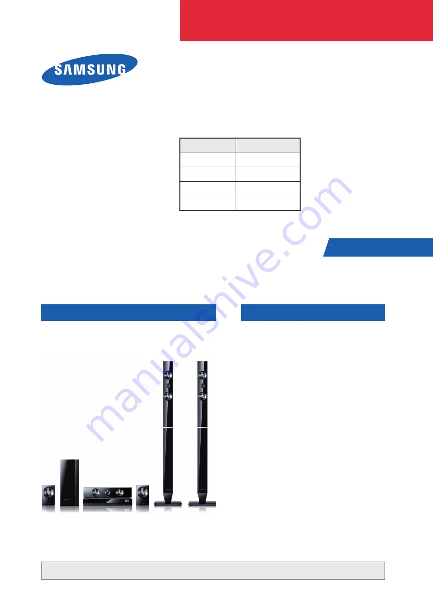
5.1CH Blu-ray Home Theater System

Refer to the service manual in the GSPN (see the rear cover) for the more information.

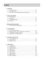
CONTENTS

1.  Precaution

2.  Product Specification

3.  Disassembly & Reassembly

4.  Troubleshooting

5.  Exploded View & Part List

6.  PCB Diagram

7.  Schematic Diagram

5.1CH Digital 
Home Theater System

Model Name : HT-C553
Model Code : HT-C553/NWT

Speaker

PS-C553

Front

PS-FC553

Center

PS-CC553

Rear

PS-RC553

Subwoofer

PS-WC553

HT-C553

Содержание HT-C553

Страница 1: ...formation CONTENTS 1 Precaution 2 Product Specification 3 Disassembly Reassembly 4 Troubleshooting 5 Exploded View Part List 6 PCB Diagram 7 Schematic Diagram 5 1CH Digital Home Theater System Model N...

Страница 2: ...domestic law GSPN Global Service Partner Network Area Web Site North America service samsungportal com Latin America latin samsungportal com CIS cis samsungportal com Europe europe samsungportal com...

Страница 3: ...4 Troubleshooting 4 1 Checkpoints by Error Mode 4 1 4 2 Measures to be taken when the Protection Circuit operates 4 17 4 3 MICOM MPEG Initialization Update 4 18 4 4 Buyer Region Code Setting Method 4...

Страница 4: ...ic Diagram 7 1 Overall Block Diagram 7 1 7 2 FRONT 7 2 7 3 TOUCH KEY 7 3 7 4 MAIN 7 4 7 5 MPEG 7 5 7 6 MICOM 7 6 7 7 AV I O 7 7 7 8 AMP 7 8 7 9 Audio AMP 1 7 9 7 10 Audio AMP 2 7 10 7 11 Audio AMP 3 7...

Страница 5: ...al Otherwise the product may be damaged Be sure to carefully read and understand the safety instructions before performing any work as the IC chips on the PCB are vulnerable to static electricity In o...

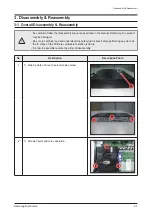
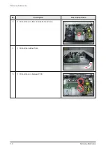
Страница 6: ...3 2 Samsung Electronics Disassembly Reassembly No Description Description Photo 3 1 Pull out the wire from cabinet front and main 4 1 Pull out the cabinet front 5 1 Pull out the wire between PCB...

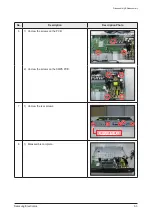
Страница 7: ...Electronics 3 3 Disassembly Reassembly No Description Description Photo 6 1 Uncrew the screws on the PCB 2 Uncrew the screws on the SMPS PCB 7 1 Uncrew the rear screws 8 1 Disassemble complete ONLY DU...

Страница 8: ...3 4 Samsung Electronics MEMO...

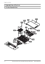
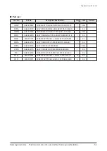
Страница 9: ...oded View Part List This Document can not be used without Samsung s authorization 5 Exploded View Part List 5 1 Product Exploded View W390 MK01A HDM01 M0014 D001A P001A T001 W391 W391 W391 W391 W391 W...

Страница 10: ...OLDER MECHA REA HT C350 ABS 10 20 10 BL 1 SNA M0014 AH94 02467D ASSY PCB MAIN HT C550 HOME THEATER CIS E 1 SA M0081 6003 001375 SCREW TAPTYPE BH B M3 L8 ZPC WHT SW 8 SA MF01A AH94 02471E ASSY PCB FRON...

Страница 11: ..._LEFT 1 SA 3 AH81 05711A STAND PILLAR ASSY FOR T0 1 SA 4 AH81 05710A STAND ASUCER ASSY FOR T0 1 SA 5 AH81 05992A SCREW 5 15BA BK TALLBOY 1 SA 6 AH81 05991A SCREW 4 15BA BK TALLBOY 4 SA Rear Speaker R...

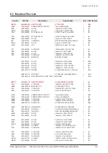
Страница 12: ...E ASSY PCB FRONT HT C550 FRONT K OK ASSY 1 SA AAC1 2203 005249 C CER CHIP 100nF 10 50V X7R TP 1608 6 SA AB335 AH61 03042B BRACKET TOP HT C550 PBS 0 3T 15 6 2 SNA AC14 2203 000189 C CER CHIP 100nF 80 2...

Страница 13: ...TP 6 6X6 6X5 4M 3 SA UIC2 0609 001189 MODULE REMOCON HORIZONTAL 16 4mm TR 1 SC VR3 2007 000766 R CHIP 330ohm 5 1 8W TP 2012 1 SA ZC165 2203 000815 C CER CHIP 0 033nF 5 50V C0G 1608 2 SA ZR24 2007 000...

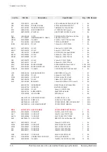
Страница 14: ...608 14 SA AR161 2007 001167 R CHIP 75ohm 5 1 10W TP 1608 16 SA AR164 2007 000076 R CHIP 330ohm 5 1 10W TP 1608 2 SA AR174 2007 000129 R CHIP 27Kohm 5 1 10W TP 1608 15 SA AR30 2007 000074 R CHIP 100ohm...

Страница 15: ...0162 R CHIP 100Kohm 5 1 16W TP 1005 18 SA DR6 2007 000831 R CHIP 39Kohm 5 1 16W TP 1005 1 SA DS01A 0401 001166 DIODE SWITCHING BAV20WS V 150V 250mA SOD 6 SA DU501 1203 001824 IC VOL DETECTOR 7042 SOT...

Страница 16: ...7 000455 R CHIP 18Kohm 1 1 10W TP 1608 1 SA MROP1 2007 000090 R CHIP 10Kohm 5 1 10W TP 1608 38 SA MX1 2801 004284 CRYSTAL SMD 27MHz 10ppm 28 AAN 20pF 30oh 1 SA ND51C2 2007 000066 R CHIP 20Kohm 1 1 10W...

Страница 17: ...5 1 16W TP 1005 1 SNA T0052 2703 002238 INDUCTOR SMD 1UH 5 2012 4 SNA T0052 2703 003362 INDUCTOR SMD 4 7uH 20 7070 1 SA T0052 2703 003768 INDUCTOR SMD 330uH 20 6060 1 SNA T0087 1203 002835 IC POSI FI...

Страница 18: ...CHIP 11Kohm 1 1 16W TP 1005 1 SA 2007 007723 R CHIP 75Kohm 1 1 10W TP 1608 1 SA 2301 001760 C FILM MPEF 100nF 10 250V TP B5xH13 5x1 6 SA 2402 001166 C AL SMD 22UF 20 50V GP TP 6 3MMX5 4MM 2 SNA 2402 0...

Страница 19: ...E RECTIFIER ES1D 200V 1A DO 214AC TP 1 SA DR01A 0402 001604 DIODE RECTIFIER MUR420 200V 4A DO 201AD 1 SA EC11 AH39 01098A HARNESS POWER HT C550 C5500 Flat Connect 1 SA EC11 AH39 01099A HARNESS POWER H...

Страница 20: ...575 C CER CHIP 220nF 10 25V X7R TP 2012 2 SNA V8932 2007 000857 R CHIP 4 3Kohm 1 1 10W TP 1608 2 SA VD11 0403 001083 DIODE ZENER UDZSNP9 1B 8 85 9 23V 200mW 2 SNA VQ4 0501 000002 TR SMALL SIGNAL KSA81...

Страница 21: ...ICROPHONE ASSY ASC MIC 10V 150 to 450uA 1 SNA C AUDI AH39 40001V CABLE AUDIO CABLE 1P 1P 3000mm 1 SA M0025 AH42 00021A ANT FM T T18011F 1 75 ohm 1800mm 1 SA BN68 01925G MANUAL FLYER WARRANTY CARD comm...

Страница 22: ...CH PANEL 4 CN1 7P SMD CONN STR MAIN PCB 2 CN9 32P FFC DIP STR AUX USB 60MM 150MM 8 CN5 15P CONN 7 ACON1 1 0P CONN SMPS CON3 15P WIRE CON2 10P CONN 5 CN2 9P DIP CON DECK 6 CN1 23P SMT CON DECK 1 3 U1 7...

Страница 23: ...6 2 Samsung Electronics PCB Diagram 6 2 FRONT PCB Top FCON1 UIC2 KIC2 U1 2 1...

Страница 24: ...ST5V 3 VFD_N27V 19 TEST 4 VFD_CLK 20 NC 5 VFD_DO 21 REMC 6 VFD_CE 22 D_P 7 VFD_GND 23 D_N 8 D5V 24 AUX_SENS 9 D5V 25 MIC_SENS 10 DGND 26 AGND 11 KEY_SCL 27 12V 12 KEY_SDA 28 MIC_MUTE 13 KET_INT 29 BU...

Страница 25: ...6 4 Samsung Electronics PCB Diagram 6 3 FRONT PCB Bottom...

Страница 26: ...Samsung Electronics 6 5 PCB Diagram 6 4 KEY PCB Top...

Страница 27: ...6 6 Samsung Electronics PCB Diagram 6 5 KEY PCB Bottom CN1 IC1 1...

Страница 28: ...Samsung Electronics 6 7 PCB Diagram 2 CN1 FROM FRONT ST Pin No Signal 1 ST5V 2 N_RESET 3 TEST 4 KEY_INT 5 KEY_SCL 6 KEY_SDA 7 DGND 6 5 1 Pin Connection...

Страница 29: ...6 8 Samsung Electronics PCB Diagram 6 6 MAIN PCB Top CN9 CN4 IC15 IC10 IC11 IC21 IC7 C N 1 CN2 AIC4 AIC19 C N 5 ACON1 IC36 1 2 5 4 3 TP1 TP1 TP3 TP2 TP3 TP4 TP5 TP6 TP4 TP5 TP6 TP7...

Страница 30: ...ON1 FROM SMPS Pin No Signal 1 16V 32V 2 16V 32V 3 16V 32V 4 GND 5 GND 6 GND 7 16V 32V 8 16V 32V 9 16V 32V 10 REF 4 CN5 FROM SMPS Pin No Signal 1 GND 2 32V 3 3 7V 4 3 7V 5 P ON 6 GND 7 GND 8 12V 9 12V...

Страница 31: ...6 10 Samsung Electronics PCB Diagram TP1 TP2 TP3 TP4 TP5 6 6 2 Test Point Wave Form TP6 TP7...

Страница 32: ...Samsung Electronics 6 11 PCB Diagram 6 7 MAIN PCB Bottom IC2 IC20 IC35 IC16 IC3 IC8 IC1 AIC22 AIC16...

Страница 33: ...6 12 Samsung Electronics PCB Diagram 6 8 SMPS PCB Top CON1...

Страница 34: ...Samsung Electronics 6 13 PCB Diagram 6 9 SMPS PCB Bottom CON2 CON3...

Страница 35: ...6 14 Samsung Electronics MEMO...

Страница 36: ...es and Underwriters Laboratories UL Publication UL1410 59 7 With the unit completely reassembled plug the AC cord directly into a 120V AC outlet With the unit s power switched from the ON to the OFF p...

Страница 37: ...AC power cord for damage Make sure that no wires or components touch thermally hot parts 8 Product Safety Notice Some electrical and mechanical parts have special safety related characteristics which...

Страница 38: ...part has not been damaged 5 Check the insulation between the blades of the AC plug and accessible conductive parts examples metal panels input terminals and earphone jacks 6 Insulation Checking Proce...

Страница 39: ...ulation of electrostatic charge 3 Do not use freon propelled chemicals These can generate electrical charges that damage ESDs 4 Use only a grounded tip soldering iron when soldering or unsoldering ESD...

Страница 40: ...g actuator technology adjusts the lens angle to the curved disc surface Defect Disc Recovery Solution can deliver a clear picture despite of scratches or other defects on the disc ASC Using ASC simply...

Страница 41: ...ise ratio 70 dB Usable sensitivity 10 dB Total harmonic distortion 0 5 DISC DVD Digital Versatile Disc Reading Speed 3 49 4 06 m sec Approx Play Time Single Sided Single Layer Disc 135 min CD 12 cm CO...

Страница 42: ...cation SPEAKER Speaker system 5 1ch Speaker System Front Rear Center Subwoofer Impedance 3 3 3 Frequency range 140Hz 20KHz 140Hz 20KHz 40Hz 160Hz Output sound pressure level 86dB W M 86dB W M 88dB W M...

Страница 43: ...170W 3 General HDMI CEC Calliope X X Deck 1 DISC 1 DISC DVD Disc Capacity 1 DVD 1 DVD Front Display 1Color VFD 1Color VFD Sleep Dimmer Compatible A V CD CD R CD RW VCD SVCD X X DVD DVD R DVD RW MP3 J...

Страница 44: ...TS 96 24 X X THX X X DTS Neo 6 X X Video Inputs Component X X Composite X X S Video X X HDMI In X X Video Outputs Component O O Composite O O HDMI Out O O S Video X X SCART Out O only Europe O only Eu...

Страница 45: ...y Europe O only Europe AM O Brazil only X Preset Memory 15 15 Remote Key Universal MBR O O Key 49 Key 60 Key Dual Voltage O Brazil only X Speaker Type Sat Tallboy Sat Tall Sat Stand O O Impedance Sat...

Страница 46: ...2 4 Accessories 2 4 1 Supplied Accessories Accessories Item Item code Remark Remote Control Battery AH59 02293A 4301 000116 Local Samsung Dealer ASC Microphone AH30 00099A Vidio Cable AH39 40001V FM...

Страница 47: ...2 8 Samsung Electronics MEMO...

Страница 48: ...L VIDEO ANALOG VIDEO PWM 6CH I2C DSP 1 IRS2053 IRF6645 F L F R IRS2053 IRF6645 F L F R IRS2053 IRF6645 C T S W IRS2053 IRF6645 C T S W IRS2053 IRF6645 R L R R IRS2053 IRF6645 R L R R The loader reads...

Страница 49: ...7 2 Samsung Electronics Schematic Diagram This Document can not be used without Samsung s authorization 7 2 FRONT POWER AUDIO...

Страница 50: ...Samsung Electronics 7 3 Schematic Diagram This Document can not be used without Samsung s authorization 7 3 TOUCH KEY POWER...

Страница 51: ...7 4 Samsung Electronics Schematic Diagram This Document can not be used without Samsung s authorization 7 4 MAIN POWER AUDIO...

Страница 52: ...Samsung Electronics 7 5 Schematic Diagram This Document can not be used without Samsung s authorization 7 5 MPEG TP2 TP3 TP4 TP5 TP6 TP4 TP6 TP5 TP2 TP3 POWER AUDIO...

Страница 53: ...7 6 Samsung Electronics Schematic Diagram This Document can not be used without Samsung s authorization 7 6 MICOM POWER AUDIO...

Страница 54: ...Samsung Electronics 7 7 Schematic Diagram This Document can not be used without Samsung s authorization 7 7 AV I O TP3 TP4 TP5 TP6 TP4 TP6 TP5 TP3 POWER AUDIO...

Страница 55: ...PR8 4 7KOHM 1 8KOHM LHPR4 1 16W LHPR12 7 5KOHM LHPC7 1 16W 50V 680PF S4560 6 5 2 LHPR14 220UH 1 16W VAA 5V 8 LHPC9 10UF 1 16W 10KOHM A_GND 100PF 50V LHPC12 LHPR15 100PF 50V LHPC13 7 100OHM VSS 5V IC32...

Страница 56: ...Samsung Electronics 7 9 Schematic Diagram This Document can not be used without Samsung s authorization 7 9 Audio AMP 1 POWER AUDIO...

Страница 57: ...7 10 Samsung Electronics Schematic Diagram This Document can not be used without Samsung s authorization 7 10 Audio AMP 2 POWER AUDIO TP1 TP1...

Страница 58: ...Samsung Electronics 7 11 Schematic Diagram This Document can not be used without Samsung s authorization 7 11 Audio AMP 3 TP1 TP1 POWER AUDIO...

Страница 59: ...7 12 Samsung Electronics Schematic Diagram This Document can not be used without Samsung s authorization 7 12 SMPS...

Страница 60: ...ooting 4 Troubleshooting 4 1 Checkpoints by Error Mode 4 1 1 Main Power No power detected Stand by LED off Change SMPS Check Main PCB No Change fuse No Check Main PCB Yes FR1 is OK ICFB5401 Pin 1 is 2...

Страница 61: ...ines between IC10 and AIC4 and AIC19 Yes Yes Replace IC10 No Check DAC3 3V of IC10 pin 86 3 Check MPEG DAC output 1 7v offset pin 83 84 85 88 89 90 of IC10 ES8398 No Check jack Input Check AMP input C...

Страница 62: ...LHPC9 10UF 1 16W 10KOHM A_GND 100PF 50V LHPC12 LHPR15 100PF 50V LHPC13 7 100OHM VSS 5V IC32 LHPC11 A_GND 22UF LHPL1 R516 R515 R514 2 1 CN12 C320 R500 8 7 D34 LHPR16 LHPL2 LHPR18 LHPR17 LHPC10 LHPC6 4...

Страница 63: ...4 4 Samsung Electronics Troubleshooting AUDIO AMP 2 page 7 10 CN9 IC11 IC7 C N 1 CN2 AIC4 AIC19 MAIN PCB Top page 6 8 Fig 4 2 2 2 2...

Страница 64: ...Samsung Electronics 4 5 Troubleshooting AUDIO AMP 3 page 7 11 CN9 AIC19 C N 5 ACON1 MAIN PCB Top page 6 8 Fig 4 3 2 2 2...

Страница 65: ...4 6 Samsung Electronics Troubleshooting MPEG page 7 5 CN4 IC10 IC11 IC7 C N 1 AIC4 IC36 MAIN PCB Top page 6 8 Fig 4 4 3 3 3...

Страница 66: ...asured at the pin 10 of IC36 Yes 1 Check if VDAC output is measured at the pin 77 of IC10 ES8398 Check if output is measured at the pin 14 of IC36 THS7374 Yes Replace the IC23 IC 2 Check if composite...

Страница 67: ...4 8 Samsung Electronics Troubleshooting MPEG page 7 5 CN4 15 IC10 IC11 IC7 C N 1 CN2 AIC4 IC36 MAIN PCB Top page 6 8 Fig 4 5 1 1 1...

Страница 68: ...Samsung Electronics 4 9 Troubleshooting AV I O page 7 7 IC10 IC11 IC36 MAIN PCB Top page 6 8 Fig 4 6 2 2 2...

Страница 69: ...2 3 Check if YDAC CADC and UDAC output is measured at the pin 76 80 and 81 of IC10 ES8398 4 5 6 Check if output is measured at the pin of 11 13 and 12 of IC36 THS7374 Yes Replace the IC23 IC Check if...

Страница 70: ...Samsung Electronics 4 11 Troubleshooting MPEG page 7 5 CN4 C15 IC10 IC11 C N 1 AIC4 IC36 MAIN PCB Top page 6 8 Fig 4 7 2 1 1 2 2 1...

Страница 71: ...4 12 Samsung Electronics Troubleshooting MPEG page 7 5 CN4 C15 IC10 IC11 C N 1 AIC4 IC36 MAIN PCB Top page 6 8 Fig 4 8 3 3 3...

Страница 72: ...Samsung Electronics 4 13 Troubleshooting AV I O page 7 7 IC11 IC36 MAIN PCB Top page 6 8 Fig 4 9 4 5 4 5 4 5...

Страница 73: ...4 14 Samsung Electronics Troubleshooting AV I O page 7 7 IC11 IC36 MAIN PCB Top page 6 8 Fig 4 10 6 6 6...

Страница 74: ...20 121 123 124 126 127 of IC10 Analog Composite Video OK but HDMI No Replace MPEG IC Yes Yes Check PLL3 3V lines and VDD1 2V lines and R150 R151 R152 value No Check Voltage pin110 pin of IC10 1 5V 1 8...

Страница 75: ...4 16 Samsung Electronics Troubleshooting 3 3 MPEG page 7 5 CN4 IC10 IC11 C N 1 AIC4 IC36 MAIN PCB Top page 6 8 Fig 4 11 1 1 1...

Страница 76: ...ture exceed 150 C 4 No supply voltage on GATE DRIVER 4 2 2 AMP Pre Inspection relating to Power Protection If you think there are problems at the AMP PCB you can check the pcb without disassemble the...

Страница 77: ...n Initialization complete Micom Update 1 Prepare or Make a DISC CD or DVD or USB that contains C550WWM SSP file for update 2 Play the USB then updating will appear on the screen then Power will go out...

Страница 78: ...M MPEG flash Version 1 On Root state Select Set up 2 Press Enter and move Support 3 Press Enter 4 Check product information SW ver on TV Display and Micom SW Ver on Front ASS y VFD Fig 4 15 Connecting...

Страница 79: ...DISC or USB then Updating will appear on the screen then Power will go out and on 3 Then DISC TRAY will open then remove the DISC or USB making the Unit as NO DISC state 4 Press STOP button of Main Un...

Страница 80: ...m Micom should be inserted the region code The set is not working properly if you don t insert the region code The region code is inserted by the remote control 1 Press the AUX button on the remote co...

Страница 81: ...60 Brazil 01 31 61 C460 90 Canada 02 32 62 China semi_mic 03 33 63 Europe 04 34 64 Indonesia Hongkong 05 35 65 Japan 06 36 66 Korea 07 37 67 Latin American 08 38 68 Mexico 09 39 69 Philippines 10 40 7...

Страница 82: ...Updating program of System Micom if Updating fail is happened it is impossible to turn on the system from stand by status The system will keep the stand by status continuously and the touch key funct...

Отзывы: