- 8 -
4. Disassembly and Reassembly
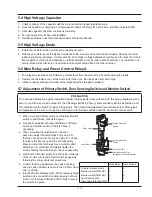
4-1 Replacement of Magnetron, Motor Assembly and Lamp
Remove the magnetron including the shield case, permanent magnet, choke coils and capacitors (all of which
are contained in one assembly).
1. Disconnect all lead wires from the magnetron and lamp.
2. Remove a screw securing air cover.
3. Remove the air cover.
4. Remove screws securing the magnetron to the wave guide.
5. Take out the magnetron very carefully.
6. Remove tow from the back panel of fan motor assembly.
7. Take out the fan motor assembly.
8. Remove the oven lamp by rotating to pull out from hole of air cover.
NOTE1
: When removing the magnetron, make sure that its antenna does not hit any adjacent parts, or it may be
damaged.
NOTE2
: When replacing the magnetron, be sure to remount the magnetron gasket in the correct position and
make sure the gasket is in good condition.
4-2 Replacement of High Voltage Transformer
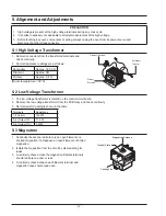
1. Discharge the high voltage capacitor.
2. Disconnect all the leads.
3. Remove the mounting bolts.
4. Reconnect the leads correctly and firmly.
PRECAUTION
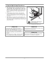
Servicemen should remove their watches whenever working close to or replacing the magnetron.
PRECAUTION
There exists HIGH VOLTAGE ELECTRICITY with high current capabilities in the circuits of the HIGHVOLTAGE
TRANSFORMER secondary and filament terminals. It is extremely dangerous to work on or near these circuits
with the oven energized.
DO NOT measure the voltage in the high voltage circuit including filament voltage of magnetron.
Содержание G2739NR
Страница 2: ... Samsung Electronics Co Ltd January 2006 Printed in Korea Code No DE68 04055A ...
Страница 31: ... 28 8 Schematic Diagrams 8 1 Schematic Diagrams This Document can not be used without Samsung s authorization ...
Страница 33: ... 30 10 Wiring Diagrams 10 1 Wiring Diagrams This Document can not be used without Samsung s authorization ...


