
4-24
Samsung Electronics
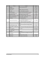
No
Parts
Procedure
Remark
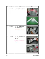
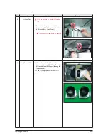
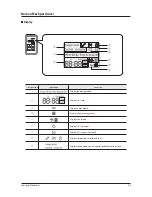
4
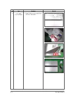
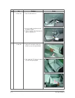
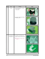
Guide Element
1) Separate the guides fixing Element.
(Use +Screw Driver.) 1 Guide is located
at each left and right end of the product.
Each guide is attached to the product with
1 bolt.
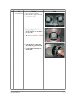
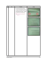
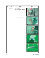
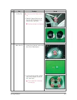
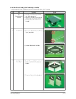
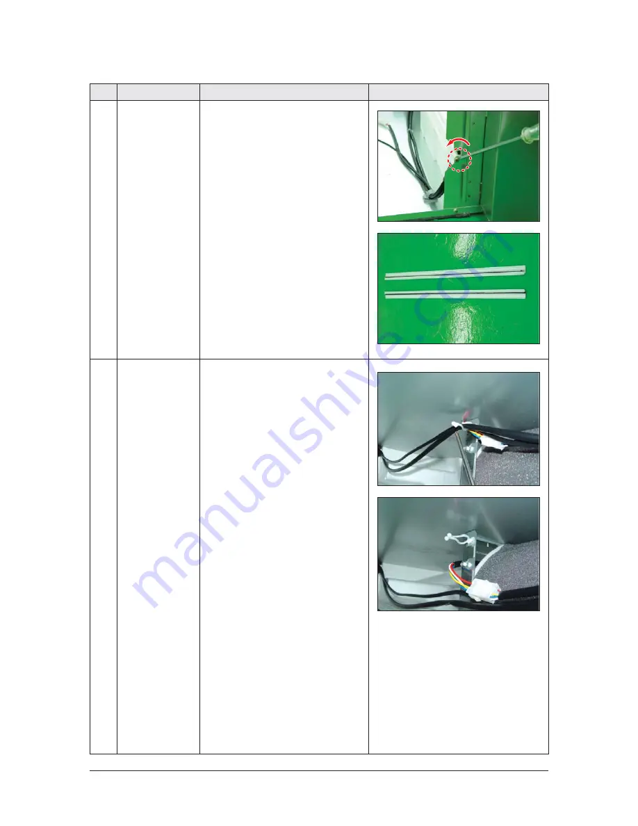
5
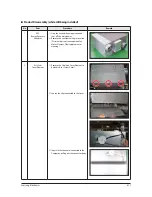
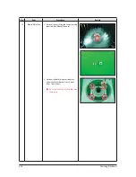
Ass’y Fan Parts
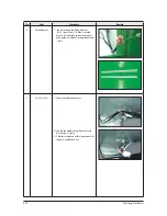
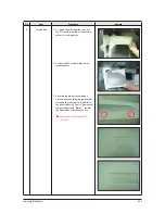
1) Separate motor connectors.
2) Loosen the holder fixing the motor wire
by twisting it slightly.
3) 2 Motors are placed within the product for
supply air and exhaust air.


