background image

E-

28

Deciding on Where to Install the Air Conditioner

When deciding on the location of the air conditioner with the owner, the following restrictions
must be taken into account.

General

Do NOT install the air conditioner in a location where it will come into contact with the following elements:

Combustible gases

Saline air

Machine oil

Sulphide gas

Special environmental conditions

If you must install the unit in such conditions, first consult your dealer.

Indoor Unit

There must be no obstacles near the air inlet and outlet.

Install the indoor unit on a surface that can support its weight.

Choose a position that enables the piping and cables to be easily connected to the outdoor unit and the
recommended length of 5m (16ft. 5in) to be respected (“L” m/ft. maximum).

Leave enough clearance beneath the indoor unit to enable the filters to be removed without hindrance.

Maintain sufficient clearance around the indoor unit, as indicated in the diagram on the page opposite.

Make sure that the water dripping from the drain hose runs away correctly and safely.

Outdoor Unit

The outdoor unit must NEVER be placed on its side or upside down, as the compressor lubrication oil will run into the
cooling circuit and seriously damage the unit.

Choose a location that is dry and sunny, but not exposed to direct sunlight or strong winds.

Do not block any passageways or thoroughfares.

Choose a location where the noise of the air conditioner when running and the discharged air do not disturb any
neighbours.

Choose a position that enables the piping and cables to be easily connected to the indoor unit and the recommended
length of 5m (16ft. 5in) to be respected (“L” m/ft. maximum).

Install the outdoor unit on a flat, stable surface that can support its weight and does not generate any unnecessary
noise and vibration.

Position the outdoor unit so that the air flow is directed towards the outside, as indicated by the arrows on the top of
the unit.

Maintain sufficient clearance around the outdoor unit, as indicated in the diagram on the page opposite.

If the outdoor unit is installed at a height, ensure that its base is firmly fixed in position; the maximum height is
“H”m/ft. (“H”: indicated in the diagram on the page opposite.)

Make sure that the water dripping from the drain hose runs away correctly and safely.

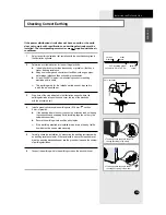
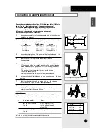
You have just purchased a split-type room air conditioner and it has
been installed by your installation specialist.

This device must be installed according to the national electrical rules.

C

C

C

C

A

A

A

A

U

U

U

U

T

T

T

T

II

II

O

O

O

O

N

N

N

N

P

REPARING THE

I

NSTALLATION

Содержание DIGIMAX A6

Страница 1: ...MANUEL D INSTALLATION DUCTLESS MINI SPLIT Cool ENDIDURA MINI END CRINO Refrigeraci n SANS CONDUIT MINI S PAR Refroidissement E S F DB68 01822A 3 ESPA OL FRAN AIS AS07A5 A6 MA AS09A5 A6 MA AS12A5 A6 MC...

Страница 2: ...d to directly contact a designated service center or the outlet at which the product was purchased 7 If the supply cord is damaged it must be replaced by a special cord or assembly available from the...

Страница 3: ...e Room Temperature Quickly 12 Removing Excess Humidity 13 Airing Your Room 14 Adjusting the Air Flow Direction Vertically 15 Adjusting the Air Flow Direction Horizontally 15 PROGRAMMING YOUR AIR CONDI...

Страница 4: ...it Air filter under the grille Air flow blades outlet Air Inlet Timer indicator STANDARD indicator NATURE indicator POWER indicator SILENCE indicator Remote Control Sensor SAVING indicator On Off 5 Wa...

Страница 5: ...Connection Valve US07A5 A6 MA US09A5 A6 MA Outdoor Unit Air Inlet Rear Air Outlet Connection Valve Inside US12A5 A6 MC Outdoor Unit Air Inlet Rear Air Outlet Connection Valve US18A5 A6 RC US24A1 A2 RC...

Страница 6: ...DRY FAN Turbo Sleep mode selection button Swing button On Timer button Off Timer button On Off Timer Set Cancel button Fan speed adjustment button Temperature adjustment buttons Temperature setting Sl...

Страница 7: ...ull advantage of the unit s features The booklet is organized as follows The following figures are shown on pages from 4 to 6 Indoor and outdoor units Remote control buttons and display They will help...

Страница 8: ...battery with on the remote control 1 2 Close the cover by sliding it back until it clicks into place 3 Use two AAA LR03 1 5V batteries Do not use old batteries or different kinds of batteries togethe...

Страница 9: ...nit To select the 5 Way function with the remote control press the 5 Way button one or more times until the desired mode is selected Each time you press the 5 Way button Each 5 Way indicator on the in...

Страница 10: ...e If necessary press the On Off button Result The 5 Way indicator on the indoor unit comes on The air conditioner starts up in the mode selected when the unit was last used The indoor unit beeps The a...

Страница 11: ...an change modes at any time N N N No o o ot t t te e e e To adjust the temperature press the TEMPERATURE buttons one or more times until the required temperature is displayed Possible temperatures are...

Страница 12: ...t was last used The indoor unit beeps 2 Press the button Result The temperature and fan settings are adjusted automatically The air conditioner cools the room as quickly as possible After 30 minutes t...

Страница 13: ...If the is not displayed at the top of the remote control press the MODE button on the remote control one or more times until it appears Result The indoor unit beeps each time you press the MODE button...

Страница 14: ...te control press the MODE button on the remote control one or more times until it appears Result The indoor unit beeps each time you press the MODE button The air conditioner runs in FAN mode The temp...

Страница 15: ...Result The blade move up and down around the base position set 3 To stop the blade moving up and down press the SWING button again N N N No o o ot t t te e e e If you switch the air conditioner Then t...

Страница 16: ...ur to 5 hours by 1 hour from 6 hours to 24 hours 1 Press the Set Cancel button to complete the setting Result The remaining time is displayed Blinking of the timer indicator stops The selected mode an...

Страница 17: ...ime is displayed Blinking of the timer indicator stops The selected mode and the temperature disappear on the display after 5 seconds The air conditioner will switch off automatically when the counter...

Страница 18: ...times until appears on the remote control Result The indoor unit beeps The air conditioner will be controlled as indicated in the illustrations below Cooling The temperature is increased by 2 F 1 C ev...

Страница 19: ...power failure occurs when the air conditioner is operating the unit is switched off When the power returns A2 A6 A1 A5 you must press the ON OFF button to restart it the air conditioner starts up agai...

Страница 20: ...r malfunction may happen if the heat exchanger freezes High humidity levels Water may condense on and drip from the surface of the indoor unit if it is used for long periods Mode Outdoor Temperature I...

Страница 21: ...e e e If you have not used the air conditioner for a long period of time set the fan going for three to four hours to dry the inside of the air conditioner thoroughly IMPORTANT Front grille Hook Body...

Страница 22: ...be too low or too high Dust may be blocking the air filter guard refer to page 21 for cleaning instructions Check that there is no obstacle in front of the outdoor unit Check that the operating mode...

Страница 23: ...N N No o o ot t t te e e e Do not remove the packing from a deodorizing filter until you wish to use the filter as it will lose its properties The air conditioner can be fitted with a deodorizing and...

Страница 24: ...1500 10 0 4 261 53 115V 60Hz 680 115V 60Hz 900 208 230V 60Hz 1320 Flare 6 35 1 4 9 52 3 8 7 0 23 AS07 MA AS09 MA AS12 MC US07 MA US09 MA US12 MC Flare 6 35 1 4 9 52 3 8 7 0 23 Flare 6 35 1 4 12 70 1 2...

Страница 25: ...Line O D Factory Pre charge Max Line length Max Height Difference mm in mm in m ft m ft m ft Dimensions Weight W X H X D Net Weight mm in Ibs W X H X D Net Weight mm in Ibs 208 230V 60Hz 8 6 1900 Flar...

Страница 26: ...E 26 INSTALLATION MANUAL...

Страница 27: ...rain Hose 34 Installing and Connecting the Indoor Unit Assembly Piping 35 Cutting Extending the Piping 36 INSTALLING THE OUTDOOR UNIT Connecting the Cables to the Outdoor Unit 37 Auxillary Circuit Bre...

Страница 28: ...o the cooling circuit and seriously damage the unit Choose a location that is dry and sunny but not exposed to direct sunlight or strong winds Do not block any passageways or thoroughfares Choose a lo...

Страница 29: ...re 600mm 24inch minimum 350mm 14inch minimum 100mm 4inch minimum 600mm 24inch minimum 100mm 4inch minimum L m ft maximum H m ft maximum Unit m ft PREPARING THE INSTALLATION Model 07 09 12 18 24 L 15 4...

Страница 30: ...s Instruction Booklet Installation Manual 1 PREPARING THE INSTALLATION OWNER S INSTRUCTIO NS MANUAL DE INSTRUCCIO NES ISTRUZIONI PER L USO MANUAL DE INSTRU ES MANUEL D UTILISATIO N GEBRAUCHSANWEISUN...

Страница 31: ...ing the indoor unit to a Then follow Steps Wall 3 Window frame 4 to 6 3 Fix the installation plate to the wall in a manner appropriate to the weight of the indoor unit If you are mounting the plate on...

Страница 32: ...mbly Cable The outdoor unit is powered from the indoor unit via the assembly cable If the outdoor unit is more than five metres away from the indoor unit the cable must first be extended to a maximum...

Страница 33: ...the screws 12 Reinstall the front grille 13 For further details on how to plug the other end of the assembly cable into the outdoor unit refer to page 37 6 Install the conduit kit The conduit kit is o...

Страница 34: ...ed for gas leaks refer to page 43 for further details Installing and Connecting the Indoor Unit Drain Hose Care must be taken when installing the drain hose for the indoor unit to ensure that any cond...

Страница 35: ...he assembly piping to each pipe tightening the nuts first manually and then with a wrench applying the following torque Pipe Outer Diameter Torque Liquid refrigerant 6 35 mm 1 4 160kg cm 11 6ft lb Gas...

Страница 36: ...rom leaking out remove all burrs at the cut end of the pipe using a reamer 4 Slide a flare nut on to the pipe and modify the flare Pipe Outer Diameter D Depth A Liquid refrigerant 6 35 mm 1 4 1 3 mm 1...

Страница 37: ...nnect the earth wires to the earth terminals Refer to the page 39 for further details on how to check that earthing is correct 4 Replace the terminal board cover carefully tightening the screw 07 09 1...

Страница 38: ...upper lower terminal of auxiliary circuit breaker It is necessary that the conduit kit for power supply to the outdoor unit be installed between auxiliary power S W and the outdoor unit the conduit k...

Страница 39: ...pposite drive the earthing electrode into position and cover the top of the electrode with the excavated soil 4 Install a green yellow insulated earthing wire 1 6 mm section 2 mm2 or greater If the ea...

Страница 40: ...round 1 Position the outdoor unit so that the air flow is directed towards the outside as indicated by the arrows on the top of the unit 2 Attach the outdoor unit to the appropriate support using anch...

Страница 41: ...of manifold gauge clockwise Make sure that pressure gauge show 0 1MPa 76cmHg after about 10minutes This procedure is very important in order to avoid gas leak Turn off the vacuum pump Remove the hose...

Страница 42: ...check that there are no gas leaks To check for gas leaks on the Then using a leak detector check the Indoor unit Flare nuts at the end of sections C and D Outdoor unit Valves on sections A and B C D B...

Страница 43: ...indoor unit with the absorbent pad make intervals of 20mm inch 3 Wind insulating tape around the pipes assembly cable and drain hose 4 Place the resulting bundle carefully in the lower part of the in...

Страница 44: ...ct any gas leakages Connection wiring Heat resistant insulation of the piping Drainage Earthing wire connection Correct operations follow the steps below 2 Press the On Off button Result The indicator...

Страница 45: ...r s instruction booklet 1 How to start and stop the air conditioner 2 How to select the operating mode and adjust the temperature and fan settings 3 How to adjust the air flow direction 4 How to set t...

Страница 46: ...ELECTRONICS Printed in Korea THIS AIR CONDITIONER IS MANUFACTURED BY ESTE AIRE ACONDICIONADO HA SIDO FABRICADO POR CE CLIMATISEUR EST FABRIQUE PAR...

Отзывы: