35
Ⅲ. ADJUSTMENT
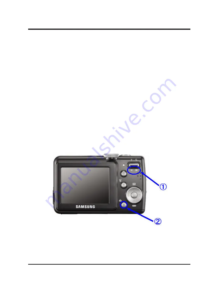
2) Upgrading the Firmware
1. Insert the SD card containing the firmware file into the camera.
※
Updating the firmware will delete all the data in the Flash memory. Be sure to back up all the data onto
your PC before updating the firmware.
The file name must be "s385n.elf". (Copy the file to the root directory of the SD card.)
2. Connect the AC adapter or a fully charged battery.
※
To upgrade the firmware, the battery level indicator on the LCD monitor must be full (level three).
3. Turn the camera off.
4. Press and hold the PLAY button for approximately 2 seconds while holding down the WIDE button.
Содержание D85
Страница 1: ......
Страница 8: ...3 LCD monitor indicator 8 Ⅰ SPECIFICATION Recording mode Image Full Status ...
Страница 14: ...Ⅱ EXPLODED VIEW AND PART LIST 14 1 3 1 2 1 3 1 2 1 1 1 4 1 MAIN ASSEMBLY ...
Страница 17: ...24 Ⅱ EXPLODED VIEW AND PART LIST 4 FRONT COVER ASSEMBLY 4 1 4 4 4 5 4 2 4 3 4 6 4 7 4 8 ...
Страница 19: ...28 Ⅱ EXPLODED VIEW AND PART LIST 6 1 6 3 6 2 6 4 6 9 6 8 6 7 6 10 6 5 6 6 6 11 6 BACK COVER ASSEMBLY ...
Страница 49: ...55 Ⅳ PATTERN DIAGRAM 1 PARTS ARRANGEMENT FOR EACH PCB ASS Y 1 MAIN_TOP ...
Страница 50: ...56 Ⅳ PATTERN DIAGRAM 2 MAIN_BOTTOM ...
Страница 51: ...57 Ⅳ PATTERN DIAGRAM 3 CCD_TOP ...
Страница 52: ...58 Ⅳ PATTERN DIAGRAM 4 CCD_BOTTOM ...
Страница 53: ...59 Ⅳ PATTERN DIAGRAM 5 STROBE_TOP ...
Страница 54: ...60 Ⅳ PATTERN DIAGRAM 6 STROBE_BOTTOM ...
Страница 55: ...61 Ⅴ CIRCUIT DIAGRAM 1 MAIN_COACH9S GPIO ...
Страница 56: ...62 Ⅴ CIRCUIT DIAGRAM 2 MAIN_COACH9S VOLATGE UI ...
Страница 57: ...63 Ⅴ CIRCUIT DIAGRAM 3 MAIN_MEMORY ...
Страница 58: ...64 Ⅴ CIRCUIT DIAGRAM 4 MAIN_USB IF ...
Страница 59: ...65 Ⅴ CIRCUIT DIAGRAM 5 MAIN_LENS DRIVER ...
Страница 60: ...66 Ⅴ CIRCUIT DIAGRAM 6 MAIN_LCD ...
Страница 61: ...67 Ⅴ CIRCUIT DIAGRAM 7 MAIN_SYSTEM BLOCK ...
Страница 62: ...68 Ⅴ CIRCUIT DIAGRAM 8 MAIN_POWER BLOCK ...
Страница 63: ...69 Ⅴ CIRCUIT DIAGRAM 9 MAIN_POWER ...
Страница 64: ...70 Ⅴ CIRCUIT DIAGRAM 10 MAIN_AD9920 ...
Страница 65: ...71 Ⅴ CIRCUIT DIAGRAM 11 CCD ...
Страница 66: ...72 Ⅴ CIRCUIT DIAGRAM 12 CCD Pin Define ...
Страница 67: ...73 Ⅴ CIRCUIT DIAGRAM 13 MODE DIAL ...
Страница 68: ...74 Ⅴ CIRCUIT DIAGRAM 14 STROBE ...
Страница 70: ...76 Ⅵ SERVICE INFORMATION Disassembling the Camera 1 Remove the 2 screws 2 Remove the 2 screws ...
Страница 71: ...77 Ⅵ SERVICE INFORMATION 3 Remove the 4 screws 4 Separate the Back Cover ...
Страница 73: ...79 Ⅵ SERVICE INFORMATION 7 Separate the Front Cover 8 Detach the sticker at the microphone part ...
Страница 74: ...80 Ⅵ SERVICE INFORMATION 9 Remove the 2 screws 10 Separate the PCB from the connector ...
Страница 76: ...82 Ⅵ SERVICE INFORMATION 13 Remove the 2 screws 14 Unsolder the battery terminals ...
Страница 77: ...83 Ⅵ SERVICE INFORMATION 15 Separate the PCB from the connector 16 Remove the 4 screws ...
Страница 78: ...84 Ⅵ SERVICE INFORMATION 17 Separate the Main PCB Bottom of the Main PCB CCD is installed ...
Страница 79: ...85 Ⅵ SERVICE INFORMATION Main PCB 18 Remove the 2 screws ...
Страница 80: ...86 Ⅵ SERVICE INFORMATION 19 Separate the Flash PCB 20 Remove the 3 screws ...
Страница 81: ...87 Ⅵ SERVICE INFORMATION 21 Separate the barrel Assy ...
Страница 89: ...95 Ⅵ SERVICE INFORMATION 15 Separate the Front Lens Group Assy 16 Separate the Guide Plate as shown below ...