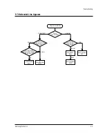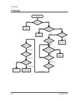
POWER
OFF
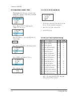
No Item Function
Range
MICOM Data
1 AGC RF AGC Adjustment
0~63
50
2 VCO PIF VCO Adjustment
0~127
63
3 SCT SUB-CONTRAST Adjustment
0~63
48
4 SCR SUB-COLOR Adjustment
0~27
13
5 STT SUB-TINT Adjustment
0~27
7
6 RC RED-CUT OFF Adjustment
0~255
0
7 GC GREEN-CUT OFF Adjustment
0~255
0
8 BC BLUE-CUT OFF Adjustment
0~255
0
9 SVC Input a Horiz line pattern
10 GG GREEN-GAIN Adjustment
0~255
127
11 BG BLUE-GAIN Adjustment
0~255
127
12 SBT SUB-BRIGHTNESS Adjustment
0~63
31
13 VA VERTICAL SIZE Adjustment
0~63
39
14 VS VERTICAL CENTER Adjustment
0
0
15 HS HORIZONTAL Phase Adjustment
0~31
15
16 SS SUB-SHARPNESS Adjustment
0~31
4
BYTE 0 : 0 0
ADJUSTMENT
PATTERN
OPTION
RESET
ADJUSTMENT
PATTERN
OPTION
RESET
ADJUSTMENT
PATTERN
OPTION
RESET
ADJUSTMENT
PATTERN
OPTION
RESET
ADJUSTMENT
PATTERN
OPTION
RESET
Initalized
Alignment and Adjustments
4-2
Samsung Electronics
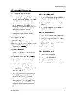
4-1-3 Adjustment in Option Mode
This adjustment is necessary whenever the
EEPROM is replaced. Input data (as marked
on the back cabinet).
Select “SET OPTION” by pressing the
Channel key twice.
Press the Volume +, - keys to enter the set
Option mode.
Press MENU to go back to the factory mode.
Select RESET with channel key.
Press key.
▼
▼
4-1-4 Service Mode Adjustments
1. The Pattern Adjustment is done only in the
factory. Do not attempt to readjust it.
2. Refer to 4-2 for other adjustments.
3. Set OPTION data.
4-1-5 Service Mode Adjustment Ratings
Note : The initial MICOM data values take
effect when IC902 is replaced.
Содержание CT331EBZX
Страница 2: ...ELECTRONICS Samsung Electronics Co Ltd JUN 1998 Printed in Korea 3K15A 0101 ...
Страница 60: ...11 Schematic Diagrams 11 1 MAIN 1 4 Schematic Diagrams Samsung Electronics 11 1 Power Line Signal Line ...
Страница 63: ...Schematic Diagrams 11 4 Samsung Electronics 11 4 MAIN 4 4 Power Line Signal Line ...


