background image

32

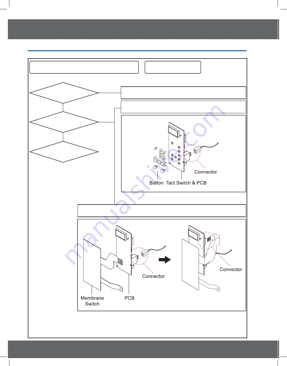
4. Troubleshooting

NO

NO

Refer to User Manual

Menbrane type

Tact type

YES

YES

Buttons of the control panel do not work.

*Inspection method

Are button pressed
in the correct order?

Is the connector of the
control panel normal?

Replace PCB.

4-3-18 If button malfunction

&0$B;(8LQGE

Содержание CM1529A-1/XEU

Страница 1: ...n the GSPN see rear cover for the more information 1 Precaution 3URGXFW 6SHFL FDWLRQ 3 Disassembly and Reassembly 4 T roubleshooting 5 PCB Diagrams 6 W iring Diagrams P BASIC CM1329 MODEL CM1529A MODEL CODE CM1529A 1 XEU 0 B 8 LQGE ...

Страница 2: ...eplacement of Fuse and H V Fuse 9 3 5 Replacement of Drive Motor Ass y Stirrier 9 3 6 Replacement of Control Box Assy and P C Board 10 3 7 Replacement of Fan Motor 11 3 8 Replacement of Tray 11 3 9 Replacement of Lamp 11 3 10 Replacement of Air Filter 12 3 11 Replacement High Voltage Capacitor 12 4 Troubleshooting 13 4 1 Error Code Numbering Rule 13 4 2 Error Code List 13 4 3 Electrical Malfunctio...

Страница 3: ...3 1 Precaution 0 B 8 LQGE ...

Страница 4: ... relay as well as the Interlock Monitor Switch The correct adjustment of these switches is described elsewhere in this manual Make sure that the fuse has the correct rating for the particular model being repaired 13 Design Alteration Warning Use exact replacement parts only i e only those that are speci ed in thedrawings and parts lists of this manual This is especially important for the Interlock...

Страница 5: ... components and adjustments If the high voltage exceeds the speci ed limits check each of the special components Note Touch chassis side first then short to the high voltage capacitor terminal by using a screwdriver H V Capacitors Negative Terminal Screwdriver PRECAUTION There exists HIGH VOLTAGE ELECTRICITY with high current capabilities in the circuits of the HIGH VOLTAGE TRANSFORMER secondary a...

Страница 6: ...del Model Basic Model New MODEL NAME CM1329 BOL CM1529A 1 XEU Power Source 230V 50Hz AC 230V 50Hz AC Power consumption Microwave 2600W 3000W Output Power 1300W IEC 705 1500W IEC 705 Operating Frequency 2 450MHz 2 450MHz Dimensions W x H x D Outside 464 x 368 x 557mm 464 x 368 x 557mm Oven cavity 370 x 190 x 370mm 370 x 190 x 370mm Volume 26Liter 26Liter Weight Net 32Kg 32Kg Export Zone Bulgarlia G...

Страница 7: ...res from the magnetron 4 Remove screws securing the duct MGT and duct fan 5 Remove the nut Àanges securing the magnetron by using a box wrench 6 Take out the magnetron very carefully NOTE1 When removing the magnetron make sure that its antenna does not hit any adjacent parts or it may be damaged NOTE2 When replacing the magnetron be sure to remount the magnetron gasket in the correct position and ...

Страница 8: ... as needed Door Handle 1 Remove hex bolts securing the upper hinge and lower hinge Then remove the door assembly 2 Insert the Àat screwdriver or thin metal plate into the gap between the door E and door C to remove Door C from the door assembly NOTE Be careful when handling Door C as is fragile NOTE The thickness of the Àatscrewdriver or thin metal plate inserted into the gap should be 0 5mm or le...

Страница 9: ...arts Explaination Photo Explaination Assy Stirrer To remove Ass y Stirrer Cover Hold side stoppers of ceiling cover with both hands and pull them in and down 1 Remove a screw securing the drive motor 2 Open the door 3 Hold side stoppers of ceiling cover Ass y Stirrer Cover with both hands and pull them in and down 4 Take the ceiling cover out of the oven cavity 5 Remove plastic clips securing the ...

Страница 10: ...ping CM1929 from the main control circuit board PCB1 4 Lift up the FPC connector hooks about 5mm upward which connects to the main control circuit board PCB1 from the tail of switch membrane of the control box assembly CM1929 5 Remove a screw securing the tapped taping to PCB1 CM1929 6 Remove Control Box Ass y 7 To replace Digitron remove 2 screws securing the PCB4 8 To replace Start Button Circui...

Страница 11: ...Explaination Assy Stirrer Tray 1 Open the door 2 Remove the tray by inserting a thin metal tool into the gap between the oven wall and the tray silicon cover 3 Insert the new tray by tilting it across the oven cavity 4 Firstly x the front part refers to the place where the silicon cover is thinner than the other 3 edges and then place the back ward part carefully and rmly NOTE Be careful when you ...

Страница 12: ...2 Lift the Air Filter off the post carefully NOTE Spacer pins are not detachable from the Air Filter 3 11 Replacement High Voltage Capacitor Parts Explaination Photo Explaination High Voltage Capacitor H V Capacitor NOTE It is not necessary to remove Magnetron in order to remove HVC 1 Remove the outer panel and back cover 2 Discharge HVT wire and H V Fuse 3 Remove HVT wire and H V Fuse 4 Remove sc...

Страница 13: ...n Check Sensor part connection of sensor housing and PCB s connector 19 Page E 12 Short 20 Page E 13 T1 Max Time Error 21 Page E 14 Dry Up No Load Insert food and restart Temp Sensor Error Code Temp Sensor Error Case E 2X Solution Page E 21 Open Check sensor part and connection of sensor housing and PCB s connector 19 Page E 22 Short 20 Page E 23 T1 Max Time Error Preheating not completed Check he...

Страница 14: ...r and restart 25 Page E 46 Primary Open Error 3minutes Check Sensor 19 Page E 47 The door opens during cooking Cancel the present mode and restart from the begining 24 Page Humidity Sensor Error Code Humidity Sensor Error Case E 6X Solution Page E 61 Open Check Sensor 19 Page E 62 Short 20 Page E 63 T1 Max Time Error 21 Page Others Error Code Others E 0X Letter Solution Page SE Key Short Error 10 ...

Страница 15: ...Is the sensor wire connected properly Does the voltage change as the humidity temperature and weight change Replace the sensor Check if the sensor wire is damaged if the housing is loose and if the sensor and the wire are properly connected Check if the voltage of the GND and sensor changes using a digital multi meter by forcefully changing the humidity temperature and weight Connect the sensor Co...

Страница 16: ...re and weight Check if the sensor and related parts such as the connector or soldering parts are slightly shorted Remove the shorted part of the temperature sensor Remove any foreign Substance from the shorted part ΊͶ Ϳ ΊͶ ΊͶ Ϳ Ϳ ΊͶ Ϳ E 12 E 22 E 28 E 32 E2A E 42 or E 62 is displayed Is the sensor shorted The sensor is out of order Replace the sensor Perform the operation again and check if it is ...

Страница 17: ...sensor or is something acting as an obstacle in front of the sensor Does it heat with completely dried food Replace the sensor If the sensor is contaminated by a foreign substance it may fail to detect the humidity Since heating completely dried food may burn the food take care Insert food and heat it again Place food with moisture into it and heat it again Remove the an foreign substance or obsta...

Страница 18: ...n and check if it is working properly S W Error Is a specific key not recognized Is the key recognized intermittently The membrane is defective Replace the Control Panel Is the key not recognized at all After Power On does the symptom continue Replace the PCB 4 3 4 Key Short Error 0 B 8 LQGE ...

Страница 19: ...ht sensor contaminated by any foreign substance Replace the sensor Check if the turntable turns abnormally because food is placed on one side only or if it turns irregularly or if it is slanted and the weight sensor is not pressed Place the turntable over the roller properly YES Remove the foreign substance Place the food in the center Has the turntable been placed over the roller properly 4 3 5 W...

Страница 20: ...it is opened or shorted intermittently Close the door Check the Door S W and the housing Was the door open during the operation Perform the operation again and check if it is working properly S W Error Is the door sensing part normal After Power On does the symptom continue Replace the PCB 4 3 6 Weight Sensor Error 0 B 8 LQGE ...

Страница 21: ...rminal is maintained over 3V continuously during the initial cooking course using a multi meter Remove any moisture of the sensor Check the sensor terminal and housing Replace the sensor ΊͶ Ϳ ΊͶ Ϳ ΊͶ Ϳ ΊͶ Ϳ E 45 is displayed Is the sensor wet S W Error Replace the PCB After Power On does the symptom continue Perform the operation again and check if it is working properly 4 3 7 Cooling Error 0 B 8 ...

Страница 22: ... ΡΖΟ ΙΠΣΥ 夞櫎垚儆Ͱ YES NO NO ͶͶ 決 旃沋 夞櫎垚儆Ͱ Έ 欪壟沗 YES YES YES NO E 51 E 53 or E 54 is displayed Has the EEPROM been inserted Is the EEPROM terminal opened or is there a short circuit EEPROM Defect Replace the EEPROM Does it work properly Perform the operation again and check if it is working properly S W Error After Power On does the symptom continue Replace the PCB 4 3 8 EEPROM Error 0 B 8 LQGE ...

Страница 23: ...inserted Is it Upper Lower Mode Is the Divider detection S W out of order Is the Divider detection S W connected properly Are the connections in the Main PCB normal Connect correctly Connect correctly wire S W Error After Power On does the symptom continue Replace the PCB Perform the operation again and check if it is working properly Remove the Divider 4 3 9 Divider Missing Error 0 B 8 LQGE ...

Страница 24: ...ponding internal temperature Is it temperature 100 C in oven Is it temperature 105 C 240 C in oven Is it temperature 245 C in oven Does same error arise S W Error S W Error Does same error arise Does same error arise Has it worked for 8 hours continuously Has it worked for 6 hours continuously Has it worked for 4 hours continuously Turn the oven off and let it cool sufficiently After Power On does...

Страница 25: ...cuit Is the temperature of the PCB over 90 C An E 2b error occurred Insert the temperature sensor An E 0b error occurred Check the Motor drive part Is the Cooling Motor rotating The temperature sensor is out of order Replace the temperature sensor Perform the operation again and check if it is working properly S W Error After Power On does the symptom continue Replace the PCB 4 3 11 Cooling Fan Mo...

Страница 26: ... E 08 E 23 E 26 is displayed Is the heater temperature very low Is the temperature sensor connected properly Is the resistance between the heater terminals more then a few M Check the heater related drive part Replace the heater Reconnect the temperature sensor properly Replace the heater Does the heater work S W Error After Power On does the symptom continue Replace the PCB Perform the operation ...

Страница 27: ...current state Press the Cancel key to cancel the current state Is this happening during the MW operation Is it happening during the Grill operation Is it happening during the Convection operation Over Time is set Over Time is set Over Time is set Over Time is set Is it happening during the Combination operation Since the max time may differ depending on the model refer to the IB For example MW Mod...

Страница 28: ...ternal temperature reached over 350 degrees Is the temperature sensor connectivity normal Is the temperature sensor connectivity normal An E 09 error occurred An E 24 E 0A error occurred Reconnect the temperature sensor properly Check and repair the heater drive part if necessary S W Error After Power On does the symptom continue Replace the PCB Perform the operation again and check if it is worki...

Страница 29: ...is working properly Is the oven in MW mode Is the internal temperature over 200 degrees Is the sensor connectivity normal An E 25 error occurred Press the Cancel key Connect it properly and try again After Power On does the symptom continue Press the Cancel key to cancel the current state 4 3 15 Swing Heater Detection Error 0 B 8 LQGE ...

Страница 30: ... Bake Toast mode Has the switch heater operated for 20 seconds Has the micro switch been detected After waiting for 20 seconds check if the micro switch has been detected The micro switch is defective Replace it Connect the micro switch properly After Power On does the symptom continue Is connectivity housing of the micro switch normal 4 3 16 Swing Heater Detection Error 0 B 8 LQGE ...

Страница 31: ...ormal NO NO Is Primary interlock switch normal Is Power Relay normal YES YES YES YES YES YES NO NO NO YES NO NO Replace switch Do check power supply circuit Do check Relay control circuit Is high voltage dioed normal Is high voltage dioed normal Is high voltage capacitor normal Is magnetron normal NO Is the IC01 output of PCB normal NO NO Checking high voltagecircuts NO NO 4 3 17 If oven malfuncti...

Страница 32: ...ser Manual Menbrane type Tact type YES YES Buttons of the control panel do not work Inspection method Are button pressed in the correct order Is the connector of the control panel normal Replace PCB 4 3 18 If button malfunction 0 B 8 LQGE ...

Страница 33: ...he latch switch operating normally Food is not heated even though an oven works Inspection method Method to control latch switch Checking high voltage circuits YES 4 3 19 If food is not heated even though an oven works 0 B 8 LQGE ...

Страница 34: ...ting with Power supply 10 CN02 Relay Connector A Terminal for Connecting with Lamp Relay Contact Load Control 11 CN03 Inrush Relay Connector A Terminal for Connecting with Vent Relay Inrush Relay1 2 Contact 12 CN04 Door switch and Humidity Sensing Connector A Terminal for Connecting with Door Switch Humidity Sensor 13 CN05 Display Connector 1 A Terminal for Connecting with Display 14 CN06 Display ...

Страница 35: ...35 6 Wiring Diagrams 6 1 Wiring Diagrams This Document can not be used without Samsung s authorization 0 B 8 LQGE ...

Страница 36: ...3 Printed in Korea GSPN GLOBAL SERVICE PARTNER NETWORK Area Web Site Europe CIS Mideast Africa gspn1 samsungcsportal com Asia gspn2 samsungcsportal com North Latin America gspn3 samsungcsportal com China china samsungportal com 0 B 8 LQGE ...

Отзывы: