background image

Refer to the service manual in the GSPN(see rear cover) for the more information.

1.  Precaution

2.  Product Specification

3.  Disassembly and Reassembly
4.  Troubleshooting
5.  Exploded Views and Part List
6.  PCB Diagrams
7.  Wiring Diagrams
8.  Schematic Diagrams

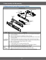
BASIC: 

CM1319


CM1619

MODEL: 

CM1319A


CM1619A


CM1919A

MODEL CODE: CM1319A/XEU


CM1619A/XEU


CM1919A/XEU

Содержание CM1319A/XEU

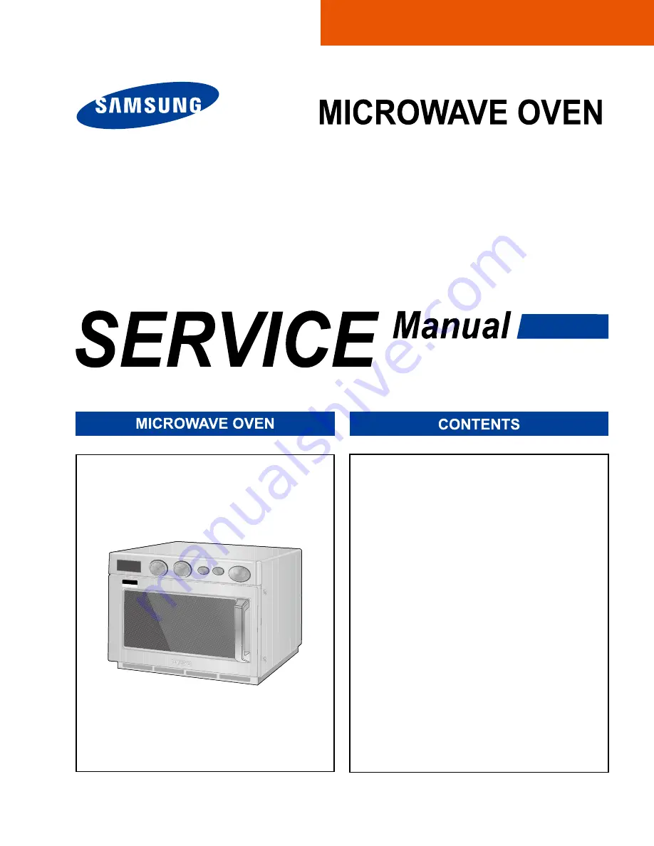
Страница 1: ...rmation 1 Precaution 2 Product Specification 3 Disassembly and Reassembly 4 Troubleshooting 5 Exploded Views and Part List 6 PCB Diagrams 7 Wiring Diagrams 8 Schematic Diagrams BASIC CM1319 CM1619 MODEL CM1319A CM1619A CM1919A MODEL CODE CM1319A XEU CM1619A XEU CM1919A XEU ...

Страница 2: ...nt of Control Box Assy and P C Board 10 3 7 Replacement of Fan Motor 11 3 8 Replacement of Tray 11 3 9 Replacement of Lamp 11 3 10 Replacement of Air Filter 12 3 11 Replacement High Voltage Capacitor 12 4 Troubleshooting 13 4 1 Error Code Numbering Rule 13 4 2 Error Code List 13 4 3 Electrical Malfunction 15 5 Exploded Views and Parts List 34 5 1 Exploded Views 34 5 2 Main Parts List 35 5 3 Door P...

Страница 3: ... 1 Precaution ...

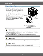
Страница 4: ...er relay as well as the Interlock Monitor Switch The correct adjustment of these switches is described elsewhere in this manual Make sure that the fuse has the correct rating for the particular model being repaired 13 Design Alteration Warning Use exact replacement parts only i e only those that are specified in thedrawings and parts lists of this manual This is especially important for the Interl...

Страница 5: ...ated components and adjustments If the high voltage exceeds the specified limits check each of the special components Note Touch chassis side first then short to the high voltage capacitor terminal by using a screwdriver H V Capacitors Negative Terminal Screwdriver PRECAUTION There exists HIGH VOLTAGE ELECTRICITY with high current capabilities in the circuits of the HIGH VOLTAGE TRANSFORMER second...

Страница 6: ... CM1319 XEU CM1619 XEU CM1919 XEU Power Source 230V 50Hz AC 230V 50Hz AC Power consumption Microwave CM1919 2600W CM1619 3000W CM1319 3200W CM1919 2600W CM1619 3000W CM1319 3200W Output Power CM1919 1850W IEC 705 CM1619 1600W IEC 705 CM1319 1300W IEC 705 CM1919 1850W IEC 705 CM1619 1600W IEC 705 CM1319 1300W IEC 705 Operating Frequency 2450MHz 2450MHz Dimensions W x H x D Outside 464 x 368 x 557mm...

Страница 7: ...adwires from the magnetron 4 Remove screws securing the duct MGT and duct fan 5 Remove the nut flanges securing the magnetron by using a box wrench 6 Take out the magnetron very carefully NOTE1 When removing the magnetron make sure that its antenna does not hit any adjacent parts or it may be damaged NOTE2 When replacing the magnetron be sure to remount the magnetron gasket in the correct position...

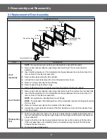
Страница 8: ... Key as needed Door Handle 1 Remove hex bolts securing the upper hinge and lower hinge Then remove the door assembly 2 Insert the flat screwdriver or thin metal plate into the gap between the door E and door C to remove Door C from the door assembly NOTE Be careful when handling Door C as is fragile NOTE The thickness of the flatscrewdriver or thin metal plate inserted into the gap should be 0 5mm...

Страница 9: ...rier Parts Explaination Photo Explaination Assy Stirrer To remove Ass y Stirrer Cover Hold side stoppers of ceiling cover with both hands and pull them in and down 1 Remove a screw securing the drive motor 2 Open the door 3 Hold side stoppers of ceiling cover Ass y Stirrer Cover with both hands and pull them in and down 4 Take the ceiling cover out of the oven cavity 5 Remove plastic clips securin...

Страница 10: ... the main control circuit board PCB1 4 Lift up the FPC connector hooks about 5mm upward which connects to the main control circuit board PCB1 from the tail of switch membrane of the control box assembly CM1929 5 Remove a screw securing the tapped taping to PCB1 CM1929 6 Remove Control Box Ass y 7 To replace Digitron remove 2 screws securing the PCB4 8 To replace Start Button Circuitry remove 3 scr...

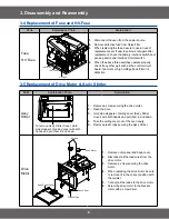
Страница 11: ...to Explaination Assy Stirrer Tray 1 Open the door 2 Remove the tray by inserting a thin metal tool into the gap between the oven wall and the tray silicon cover 3 Insert the new tray by tilting it across the oven cavity 4 Firstly fix the front part refers to the place where the silicon cover is thinner than the other 3 edges and then place the back ward part carefully and firmly NOTE Be careful wh...

Страница 12: ...eased 2 Lift the Air Filter off the post carefully NOTE Spacer pins are not detachable from the Air Filter 3 11 Replacement High Voltage Capacitor Parts Explaination Photo Explaination High Voltage Capacitor H V Capacitor NOTE It is not necessary to remove Magnetron in order to remove HVC 1 Remove the outer panel and back cover 2 Discharge HVT wire and H V Fuse 3 Remove HVT wire and H V Fuse 4 Rem...

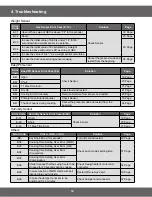
Страница 13: ...Open Check Sensor part connection of sensor housing and PCB s connector 19 Page E 12 Short 20 Page E 13 T1 Max Time Error 21 Page E 14 Dry Up No Load Insert food and restart Temp Sensor Error Code Temp Sensor Error Case E 2X Solution Page E 21 Open Check sensor part and connection of sensor housing and PCB s connector 19 Page E 22 Short 20 Page E 23 T1 Max Time Error Preheating not completed Check...

Страница 14: ...sensor and restart 25 Page E 46 Primary Open Error 3minutes Check Sensor 19 Page E 47 The door opens during cooking Cancel the present mode and restart from the begining 24 Page Humidity Sensor Error Code Humidity Sensor Error Case E 6X Solution Page E 61 Open Check Sensor 19 Page E 62 Short 20 Page E 63 T1 Max Time Error 21 Page Others Error Code Others E 0X Letter Solution Page SE Key Short Erro...

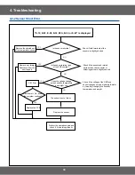
Страница 15: ...onnected Is the sensor wire connected properly Does the voltage change as the humidity temperature and weight change Replace the sensor Check if the sensor wire is damaged if the housing is loose and if the sensor and the wire are properly connected Check if the voltage of the GND and sensor changes using a digital multi meter by forcefully changing the humidity temperature and weight Connect the ...

Страница 16: ...ture and weight Check if the sensor and related parts such as the connector or soldering parts are slightly shorted Remove the shorted part of the temperature sensor Remove any foreign Substance from the shorted part YES NO YES YES NO NO YES NO E 12 E 22 E 28 E 32 E2A E 42 or E 62 is displayed Is the sensor shorted The sensor is out of order Replace the sensor Perform the operation again and check...

Страница 17: ... the sensor or is something acting as an obstacle in front of the sensor Does it heat with completely dried food Replace the sensor If the sensor is contaminated by a foreign substance it may fail to detect the humidity Since heating completely dried food may burn the food take care Insert food and heat it again Place food with moisture into it and heat it again Remove the an foreign substance or ...

Страница 18: ...n again and check if it is working properly S W Error Is a specific key not recognized Is the key recognized intermittently The membrane is defective Replace the Control Panel Is the key not recognized at all After Power On does the symptom continue Replace the PCB 4 3 4 Key Short Error ...

Страница 19: ...e weight sensor contaminated by any foreign substance Replace the sensor Check if the turntable turns abnormally because food is placed on one side only or if it turns irregularly or if it is slanted and the weight sensor is not pressed Place the turntable over the roller properly YES Remove the foreign substance Place the food in the center Has the turntable been placed over the roller properly 4...

Страница 20: ...nd if it is opened or shorted intermittently Close the door Check the Door S W and the housing Was the door open during the operation Perform the operation again and check if it is working properly S W Error Is the door sensing part normal After Power On does the symptom continue Replace the PCB 4 3 6 Weight Sensor Error ...

Страница 21: ...erminal is maintained over 3V continuously during the initial cooking course using a multi meter Remove any moisture of the sensor Check the sensor terminal and housing Replace the sensor YES NO YES NO YES NO YES NO E 45 is displayed Is the sensor wet S W Error Replace the PCB After Power On does the symptom continue Perform the operation again and check if it is working properly 4 3 7 Cooling Err...

Страница 22: ...M 단자가 Open Short 되었는가 YES NO NO EEPROM이 삽입 되었는가 S W 오동작 YES YES YES NO E 51 E 53 or E 54 is displayed Has the EEPROM been inserted Is the EEPROM terminal opened or is there a short circuit EEPROM Defect Replace the EEPROM Does it work properly Perform the operation again and check if it is working properly S W Error After Power On does the symptom continue Replace the PCB 4 3 8 EEPROM Error ...

Страница 23: ...vider inserted Is it Upper Lower Mode Is the Divider detection S W out of order Is the Divider detection S W connected properly Are the connections in the Main PCB normal Connect correctly Connect correctly wire S W Error After Power On does the symptom continue Replace the PCB Perform the operation again and check if it is working properly Remove the Divider 4 3 9 Divider Missing Error ...

Страница 24: ...for the corresponding internal temperature Is it temperature 100 C in oven Is it temperature 105 C 240 C in oven Is it temperature 245 C in oven Does same error arise S W Error S W Error Does same error arise Does same error arise Has it worked for 8 hours continuously Has it worked for 6 hours continuously Has it worked for 4 hours continuously Turn the oven off and let it cool sufficiently After...

Страница 25: ... short circuit Is the temperature of the PCB over 90 C An E 2b error occurred Insert the temperature sensor An E 0b error occurred Check the Motor drive part Is the Cooling Motor rotating The temperature sensor is out of order Replace the temperature sensor Perform the operation again and check if it is working properly S W Error After Power On does the symptom continue Replace the PCB 4 3 11 Cool...

Страница 26: ...ES NO YES NO E 08 E 23 E 26 is displayed Is the heater temperature very low Is the temperature sensor connected properly Is the resistance between the heater terminals more then a few MΩ Check the heater related drive part Replace the heater Reconnect the temperature sensor properly Replace the heater Does the heater work S W Error After Power On does the symptom continue Replace the PCB Perform t...

Страница 27: ...l the current state Press the Cancel key to cancel the current state Is this happening during the MW operation Is it happening during the Grill operation Is it happening during the Convection operation Over Time is set Over Time is set Over Time is set Over Time is set Is it happening during the Combination operation Since the max time may differ depending on the model refer to the IB For example ...

Страница 28: ...Has the oven internal temperature reached over 350 degrees Is the temperature sensor connectivity normal Is the temperature sensor connectivity normal An E 09 error occurred An E 24 E 0A error occurred Reconnect the temperature sensor properly Check and repair the heater drive part if necessary S W Error After Power On does the symptom continue Replace the PCB Perform the operation again and check...

Страница 29: ...ck if it is working properly Is the oven in MW mode Is the internal temperature over 200 degrees Is the sensor connectivity normal An E 25 error occurred Press the Cancel key Connect it properly and try again After Power On does the symptom continue Press the Cancel key to cancel the current state 4 3 15 Swing Heater Detection Error ...

Страница 30: ...he oven in Bake Toast mode Has the switch heater operated for 20 seconds Has the micro switch been detected After waiting for 20 seconds check if the micro switch has been detected The micro switch is defective Replace it Connect the micro switch properly After Power On does the symptom continue Is connectivity housing of the micro switch normal 4 3 16 Swing Heater Detection Error ...

Страница 31: ...duit normal NO NO Is Primary interlock switch normal Is Power Relay normal YES YES YES YES YES YES NO NO NO YES NO NO Replace switch Do check power supply circuit Do check Relay control circuit Is high voltage dioed normal Is high voltage dioed normal Is high voltage capacitor normal Is magnetron normal NO Is the IC01 output of PCB normal NO NO Checking high voltagecircuts NO NO 4 3 17 If oven mal...

Страница 32: ...r to User Manual Menbrane type Tact type YES YES Buttons of the control panel do not work Inspection method Are button pressed in the correct order Is the connector of the control panel normal Replace PCB 4 3 18 If button malfunction ...

Страница 33: ...O Is the latch switch operating normally Food is not heated even though an oven works Inspection method Method to control latch switch Checking high voltage circuits YES 4 3 19 If food is not heated even though an oven works ...

Страница 34: ...76 M155 P061 U003 M129 M102 M036 R066 P018 P019 P017 M029 P046 M076 M020 M024 P074 M051 M001 M015 W002 P047 M049 M066 M078 P001 M035 P075 B013 B001 B005 B002 B012 B001 B006 P069 M019 Z781 P048 B018 M048 M017 Z016 M011 M087 T002 T108 M038 M042 M052 M041 M040 M039 ...

Страница 35: ...2 M076 2301 001204 C FILM LEAD PEF 1 50UF 5TO 10 450VAC 1 SNA 1 2 M039 2501 001277 C OIL 0 80UF 2100V CLASS P AL CAN T 1 SA CM1319 1 2 M039 2501 001282 C OIL 1 00UF 2100V CLASS P AL CAN T 1 SA CM1619 1 2 M039 2501 001284 C OIL 1 10UF 2100V CLASS P AL CAN T 1 SA CM1919 1 2 M024 DE31 10180A MOTOR VENTILATION SMV 1829EA 240V50HZ 22 1 SA 1 2 M040 DE61 00421A BRACKET HVC CM1829 SECC T0 8 1 SA 1 2 M112 ...

Страница 36: ...SA 1 2 B006 DE66 40062A LATCH BODY 1 SA 1 2 B012 DE66 90107A LEVER SWITCH U PBT CM 1819 1 SA 1 2 B013 DE66 90108A LEVER SWITCH L PBT CM 1819 1 SA 1 1 W002 DE96 00503A ASSY WIRE HARNESS A CM1929 230V 50HZ VI 1 SA 1 1 M015 DE96 00639B ASSY POWER CORD CEE F CEE 250V 15A 2200 1 SA 1 1 T002 DE97 00319A ASSY TRAY CERAMIC CM1829 1 SA 1 2 T108 DE61 00170A FOOT TRAY CM1049 URETHANE WHT 1 SNA 1 2 T002 DE74 ...

Страница 37: ...5EG1 KEC T3 0 W24 5 L2 1 SNA 1 2 D019 DE64 20123A HANDLE CM 1819 ZN DICASTING C 1 SA 1 2 D006 DE64 40298A DOOR C PP 1 SA 1 2 D021 DE64 90145A DECORATION DOOR ABS CM 1819 CM 1 1 SA 1 2 D022 DE64 90146A DECORATION COV DOOR STS CM 1819 1 SA 1 2 D024 DE67 20174D SCREEN DOOR B CM1319 GLASS T3 2 W198 5 1 SA CM1319 1 2 D024 DE67 20174H SCREEN DOOR B CM1619 GLASS 3 2 198 5 36 1 SA CM1619 1 2 D024 DE67 201...

Страница 38: ...B TIMER RESIN ABS NI CR PLA 1 SA 1 3 C010 DE66 20211A BUTTON SELECT NI CR PLATING CM 1 1 SA 1 3 C009 DE67 40161A WINDOW DISPLAY RESIN PMMA 82555 CM 181 1 SA 1 3 C020 DE70 30126A PANEL BASE RESIN ABS ME CM 1819 1 SNA 1 3 C021 DE71 60427A COVER PANEL STS430 T0 5 ME CM 1829 1 SA 1 3 C022 DE71 60428B COVER PANEL L L CM1019 ABS CM 1 SA 1 3 C023 DE71 60429B COVER PANEL L R CM1019 ABS CM 1 SA 1 3 C019 DE...

Страница 39: ...EW A 2S 4X10 FEFZY 3 SNA O P C PANEL BODY LATCH 1 1 DE60 10199A SCREW WASHER MSWR18C 4 L10 TH WASHER 7 SA SUP FAN DUCT OVEN DUCT MGT R DUCT MGT L 1 1 DE60 20014A BOLT FLANGE M5 L10 MSWR3 FEFZY 2 SA HINGE UPPER HINGE DOOR LOWER 1 1 DE60 30015A NUT FLANGE M5 P0 8 MSWR10 FEFZY 1 SA MGT 1 2 6006 001176 SCREW ASSY TAPT WT PH M4 L8 ZPC YEL 1 SNA 1 2 DE60 10082I SCREW A 2S 4X10 FEFZY 2 SNA VENT MOTOR C F...

Страница 40: ...Power supply 10 CN02 Relay Connector A Terminal for Connecting with Lamp Relay Contact Load Control 11 CN03 Inrush Relay Connector A Terminal for Connecting with Vent Relay Inrush Relay1 2 Contact 12 CN04 Door switch and Humidity Sensing Connector A Terminal for Connecting with Door Switch Humidity Sensor 13 CN05 Display Connector 1 A Terminal for Connecting with Display 14 CN06 Display Connector ...

Страница 41: ...41 7 Wiring Diagrams 7 1 Wiring Diagrams This Document can not be used without Samsung s authorization ...

Страница 42: ...C246M IC101 B 1 D 5 E 4 2 S2 S3 3 S7 7 8 OJ01 TNY266P SMW250 05V_WHT CN04 1 2 3 4 5 TR10 KRC246M 5V C15 1nF KRC246M TR14 12V 100nF C02 D09 1N4148M MTZJ12B 5V 1N4148M D06 5V ZD102 10K R04 R08 100K OJ03 DU12D1 1PR RY01 R46 R30 47K 200K PTC2 390M D101 UF4007 D03 1N4148M RY04 FTR F3AA012E 1N4148M D13 FH 51H FUSE1 1K R37 1nF C14 2K OR01 100nF C01 OR02 2K FTR F3AA012E RY03 R38 TR06 KRC246M 10K 5V OJ02 R...

Страница 43: ...ungportal com Latin America latin samsungportal com CIS cis samsungportal com Europe europe samsungportal com China china samsungportal com Asia asia samsungportal com Mideast Africa mea samsungportal com Samsung Electronics Co Ltd August 2007 Printed in Korea Code No DE68 04552A ...

Отзывы: