


19
English
Installation Pr
oc
edur
e
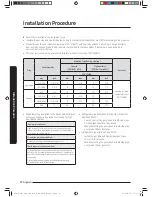
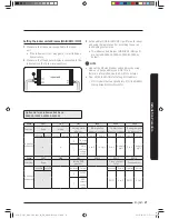
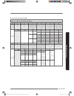
• Calculation
– Installing with 1 sort wire.
2.5[mm²]
(0.004 inch²)
-2.2 [V]
-2.0 [V]
220 [V]
-(2.2+2.0+1.8+1.5+1.3+1.1+0.9+0.7+0.4+0.2)=-11.2 [V]
208.8 [V] :
Applicable
Within 187V
to 253V
······· 2.5[mm²] (0.004 inch²) ·······
2.5[mm²]
(0.004 inch²)
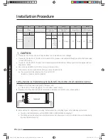
– Installing with 2 different sort wire.
4.0[mm²]
(0.006 inch²)
-1.4 [V]
-1.2 [V]
220 [V]
-(1.4+1.2+1.8+1.5+1.3+1.1+0.9+0.7+0.4+0.2)=-10.5 [V]
209.5 [V] :
Applicable
Within 187V
to 253V
······· 2.5[mm²] (0.004 inch²) ·······
4.0[mm²]
(0.006 inch²)
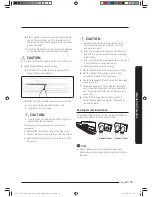
CAUTION
• Select the power cable in accordance with relevant
local and national.
• Wire size must comply with local and national code.
• You should connect the power cable into the power
cable terminal and fasten it with a clamp.
• The unbalanced power must be maintained within 10%
of supply rating among whole indoor units.
• If the power is unbalanced greatly, it may shorten
the life of the condenser. If the unbalanced power is
exceeded over 10% of supply rating, the indoor unit is
protected, stopped and the error mode indicates
• Connect the power cable to the auxiliary circuit breaker.
An all pole disconnection from the power supply must be
̈͝ʀͱθΧͱθɇϩʪʒ̈͝ϩ˵ʪ˙̈уʪʒӥθ̈͝˝ࣄ्ߤ͔͔࣍ߢࢥߩ࣎ࣅࢋ
• You must keep the cable in a protection tube.
• Maximum length of power cables are decided within
10% of power drop. If it exceeds, you must consider
another power supplying method.
• The circuit breaker(MCCB, ELB) should be considered
more capacity if many indoor units are connected from
one breaker.
• Use round pressure terminal for connections to the
power terminal block.
• For wiring, use the designated power cable and
connect it firmly, then secure to prevent outside
pressure being exerted on the terminal board.
• Use an appropriate screwdriver for tightening the
terminal screws. A screwdriver with a small head will
strip the head and make proper tightening impossible.
• Over-tightening the terminal screws may break them.
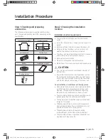
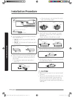
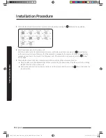
Step 13 Optional: Extending the power
cable
1
Prepare the following tools.
Tools
Spec
Shape
Crimping pliers
MH-14
Connection sleeve
[mm(inch)]
20xØ6.5
(0.79xØ0.26)
(HxOD)
Insulation tape
[mm(inch)]
Width 19
(0.75)
Contraction tube
[mm(inch)]
70xØ8.0
(2.76xØ0.32)
(LxOD)
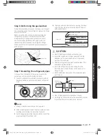
2
As shown in the figure, peel off the shields from the
rubber and wire of the power cable.
• Peel off 20mm (13/16 inch) of cable shields from
the pre-installed tube.
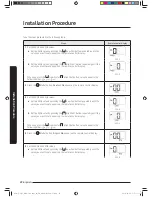
CAUTION
• For information about the power cable
specifications for indoor and outdoor units, refer to
the installation manual.
• After peeling off cable wires from the pre-installed
tube, insert a contraction tube.
k}t㨰䛙~TmGX ptluki]_TW^\\WhTWXUGGGX`
YWX_TWYTY_GGG㝘㤸GXXaXXa[\