


22
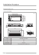
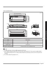
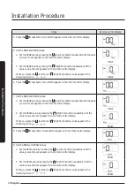
Installation Procedure
English
Installation Pr
oc
edur
e
2
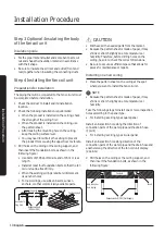
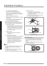
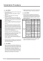
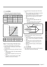
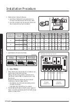
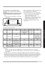
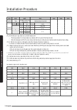
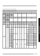
Selecting the crimping terminal lug
• Select the crimping terminal lug based on the
nominal cross-sectional size of the power cable.
• Cover the connection part of the power cable and
the crimping terminal lug to insulate it.
Silver solder
B
d2
F
L
t
E
d1
D
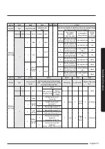
Nominal cross-
sectional size
Nominal diameter
of thread
B
D
d1
E
F
L
d2
t
Basic
size
Tolerance Basic
size
Tolerance Basic
size
Tolerance Min. Min. Max. Basic
size Tolerance Min.
1.5
4
6.6
±0.2
3.4
+0.3
-0.2
1.7
±0.2
4.1
6
16
4.3
+0.2
0
0.7
4
8
2.5
4
6.6
±0.2
4.2
+0.3
-0.2
2.3
±0.2
6
6
17.5
4.3
+0.2
0
0.8
4
8.5
4
4
9.5
±0.2
5.6
+0.3
-0.2
3.4
±0.2
6
5
20
4.3
+0.2
0
0.9
3
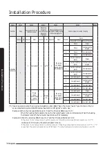
Specifications of the terminal blocks
(Unit: mm)
AC power:
M4 screw
Communication:
M3 screw
Communication:
M3.5 screwELB
11
13
18
6.62
7.62
10
7.5
9.0
13
.8
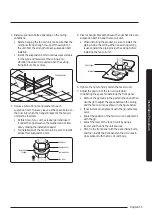
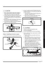
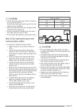
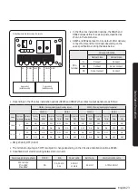
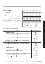
CAUTION
• When installing the product, be sure to install a 2-way
electric valve on the water inlet pipe.
When connecting a 2-way electric value, be sure to
check the correct sub PBA terminals as shown in the
figure below.
Incorrect terminal connection may cause product
malfunction. (Valve: Purchased at site)
– Specification: AC 220 to 240V (Operating current
must be 0.3A or less.)
– Applicable type: ON / OFF startup contact
• The standard specification is that the power supply for
the fan coil unit should be separate from that for a heat
source such as a chiller.
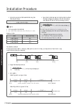
N
N
1-NO 1-NC
N
2-NO 2-NC
Wiring diagram when connecting a 2-way valve
2-Way valve1
(installed on site)
2-Way valve2
(installed on site)
Содержание AGTN1DKH Series
Страница 41: ...41 English Appendix Memo ...
Страница 42: ...42 Memo English Appendix ...
Страница 43: ...43 English Appendix ...
Страница 44: ...DB68 09309A 00 ...