3
.
Installing the Product
English 8/2020. Rev 0.3
43
3.10.5
Busbar Installation
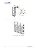
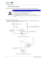
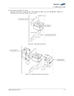
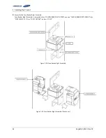
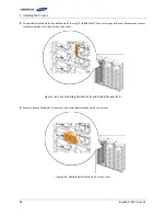
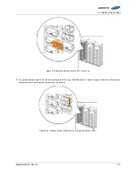
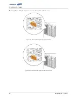
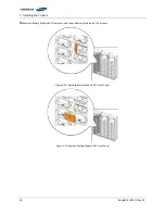
Connect the power busbars between modules
Verify with a voltmeter that no power is present on the system.
Use lock out/tag out procedures to secure the UPS and batteries.
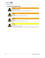
CAUTION
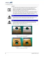
Please follow the instructions to protect the module BMS against damage.
Important: DO NOT deviate from the sequence of steps below.
The system’s voltage will increase proportionally as battery modules are connected. Exercise
extreme caution to prevent the terminals from contacting anything except their intended
mounting points.
Terminals and their connected wires have either positive or negative polarity (Positive: B+, P+;
Negative: B-, P-). The polarity of a terminal or a wire connected to the terminal is on the front
of each module and SMU. Exercise extreme caution to prevent the terminals and/or wires with
opposite polarity from contacting with each other.
It is recommended not to touch the battery po) or negative(-) terminal for the batteries
with rack frame. There is no evidence of dielectric breakdown because of electrical isolation
between the battery positive (+) or negative (-) terminals and rack frame. However, it is
recommended not to touch them for safety because It is possible to touch between battery
positive (+) and negative (-) through the rack frame.
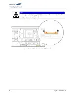
NOTICE
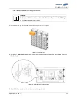
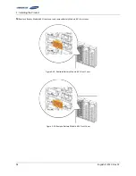
Connect the power busbar with an M8 screw for battery module terminals
The fastening torque should be 12.2–14.0 Nm (124–142 kgf/cm).
Use an insulated torque wrench extension with a 13 mm socket.
After torqueing, torque mark the screws using a colored marker or a torque seal.
NOTICE
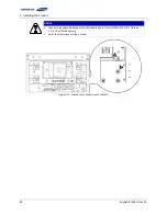
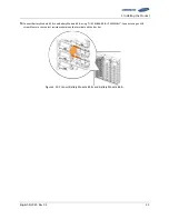
Connect the power bus-bar with an M12 screw for SMU terminals
The fastening torque should be 30 Nm/300 kgf∙cm.
Use an insulated torque wrench extension with a 19 mm socket.
After torqueing, torque mark the screws using a colored marker or a torque seal.
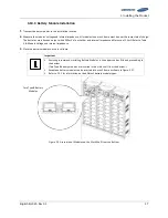
Important
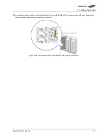
The power terminals, such as “B+,” “B-,” “P+,” and “P-,” of the module and SMU are covered
with the power terminal cover to guard against a short circuit.
At each step in this process, you must remove the cover prior to connecting a power busbar
and reattach the cover immediately after connecting the power busbars.
Содержание 9395
Страница 1: ...English 8 2020 Rev 0 3 LIB System for UPS U6A4 Installation Manual 136S ...
Страница 4: ...English 8 2020 Rev 0 3 ...
Страница 10: ...Important Safety Instructions vi English 8 2020 Rev 0 3 ...
Страница 17: ...Table of Contents English 8 2020 Rev 0 3 vii ...
Страница 18: ......
Страница 78: ...3 Installing the Product 60 English 8 2020 Rev 0 3 Figure 3 63 Remove Battery Modules 9 s Front Cover ...
Страница 117: ...3 Installing the Product English 8 2020 Rev 0 3 99 Figure 3 130 AC Input Terminals of SMPS Assembly 1 Phase Type B ...
Страница 126: ...Memo ...
Страница 127: ...Memo ...
Страница 128: ...Memo ...
Страница 129: ...www SamsungSDI com ...


