5
Range switch
- When pressed in, the LED in the switch lights and the Equalizer sliders cut or boost each
frequency area by up to 6 dB, allowing fine frequency curves to be set. When out (in the up position), the
Equalizer sliders cut or boost each frequency area by up to 12 dB, allowing course control. The setting of
the ±12dB switch also affects how Cut Only operates—see #3 on the previous page for more information.
6
Power switch
- Use this to turn the power on and off.
7
Bypass switch
- When not pressed in, the equalization circuitry is made inactive so that the signal pass-
es through unaffected, regardless of the settings of the Equalizer or Level sliders. When pressed in, the
LED in the switch and the sliders light green and the equalization circuitry affects the signal as per the
setting of the front panel Equalizer and Level sliders (see #1 and #2).
8
LOW CUT switch-
When pressed in, the LED in the switch lights yellow and the variable highpass filter is
applied to the signal. Using the Low Cut can be highly effective in removing rumble and other low fre-
quencies.
9
LOW CUT control-
When the Low Cut switch is pressed in, the varable low cut control is active. You can
adjust the point at which the low frequencies begin to roll off with a frequency range of from 15 to 200 Hz.
5
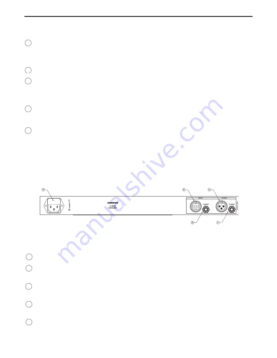
A
AC input fuseholder
- Connect the supplied heavy gauge 3-pin “IEC” power cable here.
B
Balanced XLR jack input
- Electronically balanced XLR jack input. Wiring is as
follows: pin 2 hot, pin 3 cold, and pin 1 ground.
C Balanced
XLR jack
output
- Electronically balanced XLR jack output. Wiring is as fol-
lows: pin 2 hot, pin 3 cold, and pin 1 ground.
D Balanced
1/4" TRS jack
input
- Electronically balanced 1/4" TRS jack input. Wiring is as
follows: tip hot, ring cold, and sleeve ground.
E
Balanced 1/4" TRS jack output
- Electronically balanced 1/4" TRS jack output. Wiring
is as follows: tip hot, ring cold, and sleeve ground.
Controls and Functions
REAR PANEL LAYOUT
Содержание S curve 131
Страница 1: ...S C l a s s S i g n a l P r o c e s s o r s 31 BAND EQUALIZER ...
Страница 19: ...17 S curve 131 Block Diagram ...


