Samson PL1602 Скачать руководство пользователя страница 6

Guided Tour - Channels

1:  Equalizer (white) - These knobs determine the amount of boost or attenuation in each
of two frequency areas.  The high and low frequency knobs provide 15 dB of cut or boost
at 10 kHz and 100 Hz, respectively, with both utilizing a shelving curve.  The EQ setting
affects both the odd- and even-numbered channel inputs, although the signals remain
separate.  A center detent in each knob (at the “0” position) indicates no boost or attenua-
tion (that is, flat response).  As each knob is turned clockwise from the “0” position, the
frequency area is boosted; as it is turned counterclockwise from the “0” position, the
frequency area is attenuated.  For more information on the application of EQ, see the
“Using Equalization” section on page 17 of this manual.

2:  Level - This knob (purposely made a little bigger than the others so you can find it
easily in low-light situations) simultaneously controls the volume of both the odd- and even-
numbered channel inputs (the relative volumes of the two can be adjusted with the Balance
knob, as described in #4 below). In practice, you will use the Level controls to  continuously
adjust the loudnesses of the various signals being blended together by the PL 1602.
The “0” (2 o’clock) position of the knob indicates unity gain (no level attenuation or boost).
Moving the knob counterclockwise from the “0” position (towards “

”) causes the signal to

be attenuated (at the very bottom, it is attenuated infinitely—in other words, there is no
sound).  Moving it clockwise from the “0” position (towards “+10”) causes the signal to be
boosted by as much as 10 dB.

For best signal-to-noise ratio, all Level controls for channels carrying signal should general-
ly be kept at or near the “0” position.  Channels that are unused should have their Level
controls kept fully counterclockwise at their “

” (minimum) level.  See the “Setting the

Correct Gain Structure” section on page 12 in this manual for more information.

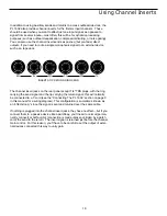
3:  Auxiliary sends (blue) - These knobs (labeled “Aux 1L” and “Aux 2R”) allow you to
route signal to either or both of the PL 1602’s two monophonic Auxiliary outputs.  These
are typically used to route signal to outboard effects devices.  When a pair of channel
inputs (that is, both odd-numbered and even-numbered) are connected, the odd-numbered
(left) input signal can only be routed to Aux 1L, while the even-numbered (right) input can
only be routed to Aux 2R.  When only the odd-numbered (left) input is connected, the sig-
nal can be routed to both Aux 1L and Aux 2R.  When only the even-numbered (right) input
is connected, the signal can only be routed to Aux 2R.  When an Aux send knob is at the
“0” (2 o’clock) position, the signal is routed with unity gain (that is, no boost or attenuation).
As each Aux send knob is turned clockwise from the “0” position, the signal is boosted; as
it is turned counterclockwise from the “0” position, it is attenuated.  Both Aux sends are
pre-fade (that is, the level of the signal is unaffected by the position of its Level control,
Trim control [in the case of channels 1 and 3] or by the Left/Right faders) but post-EQ.

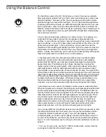
4:  Balance (dark gray) - When a pair of channel inputs (that is, both odd-numbered and
even-numbered) are connected, the odd-numbered (left) input signal is automatically
panned hard left and the even-numbered (right) input signal is automatically panned hard
right.  In this case, the “Balance” knob controls the relative levels of the paired input
signals.  When the knob is placed at its center detented position, both signals are at equal
strength.  When moved left of center, the odd-numbered (left) input signal remains at the
same strength but the even-numbered (right) input signal is attenuated; when the knob is
moved right of center, the even-numbered (left) input signal remains at the same strength
but the odd-numbered (right) input signal is attenuated.  When placed fully counterclock-
wise, only the odd-numbered (left) input signal is heard (panned hard left); when placed
fully clockwise, only the even-numbered (right) input signal is heard (panned hard right).
When only the odd-numbered (left) input is connected, the Balance knob functions as a
constant level Pan control, allowing you to continuously place the incoming signal any-
where in the left-right stereo field.  For more information, see the “Using the Balance
Control” section on page 16 in this manual.

4

-15

+15

0

-15

+15

HIGH

0

AUX 1L

+10

0

LOW

+10

LEVEL

0

AUX 2R

+10

0

BALANCE

CHANNEL 1/2

1

3

2

4

Содержание PL1602

Страница 1: ......

Страница 2: ...Grounding Techniques 14 Using the Balance Control 16 Using Equalization 17 Using Aux Sends and Returns 18 Using Channel Inserts 19 Applications Notes 20 Using The PL 1602 As A Main Live Mixer 20 Using The PL 1602 As An Onstage Monitor Mixer 21 Using The PL 1602 As A Keyboard Submixer 22 Linking The PL 1602 With Other Mixers 23 Appendix A Block Diagram 24 Appendix B Changing the PL 1602 Voltage 25 ...

Страница 3: ...balancing equalization auxiliary sends and returns and channel inserts in detail Finally we ll wrap things up with a series of applications notes describing a number of ways to use the PL 1602 reference Appendices and full specifica tions You ll also find a warranty card enclosed please don t forget to fill it out and mail it in so that you can receive online technical support and so we can send y...

Страница 4: ...reo auxiliary returns which can be used as four monophonic returns Both sends are pre fader but post equalizer Independent 2 band equalization for each channel with 15 dB of cut or boost for low 100 Hz and high 10 kHz frequencies Balance controls for each channel and Aux return that allow you to blend the relative levels of stereo inputs Channel inserts are provided for channels 1 6 enabling you t...

Страница 5: ...AUX 2R 10 0 R BALANCE L 15 15 0 15 15 HIGH 0 AUX 1L 10 0 LOW 10 LEVEL 0 AUX 2R 10 0 R BALANCE L 15 15 0 15 15 HIGH 0 AUX 1L 10 0 LOW 10 LEVEL 0 AUX 2R 10 0 R BALANCE L 15 15 0 15 15 HIGH 0 AUX 1L 10 0 LOW 10 LEVEL 0 AUX 2R 10 0 R BALANCE L 15 15 0 15 15 HIGH 0 AUX 1L 10 0 LOW 10 LEVEL 0 AUX 2R 10 0 R BALANCE L AUX 1 2 RETURN 10 0 AUX3 4 RETURN 10 0 R L R L 0 15 15 0 0 10 PHONES LEFT RIGHT PL 1602 ...

Страница 6: ...ally used to route signal to outboard effects devices When a pair of channel inputs that is both odd numbered and even numbered are connected the odd numbered left input signal can only be routed to Aux 1L while the even numbered right input can only be routed to Aux 2R When only the odd numbered left input is connected the sig nal can be routed to both Aux 1L and Aux 2R When only the even numbere...

Страница 7: ...put signal is attenuated when the knob is moved right of center the right input signal remains at the same strength but the left input signal is attenuated When placed fully counterclockwise only the left input signal is heard panned hard left when placed fully clockwise only the right input signal is heard panned hard right These radical positions are useful when you are using a stereo Aux return...

Страница 8: ...ere just before leaving the PL 1602 via its left and right Main Out jacks see 7 on page 8 for more information The 0 position of each fader indicates unity gain no level attenuation or boost Moving each fader down from the 0 position towards causes the signal to be attenuated at the very bottom it is attenuated infinitely in other words there is no sound Moving each fader up from the 0 position to...

Страница 9: ...nserted into these inputs but you ll get better signal quality and less outside noise and hum if you use balanced lines When connecting monophonic as opposed to stereo signal sources use the left odd numbered inputs the Balance control for that channel pair will then act as a constant level pan control see the Using the Balance Control section on page 16 for more information The Connecting The PL ...

Страница 10: ...ctor plugs can also be inserted into these outputs but you ll get better signal quality and less outside noise and hum if you use balanced lines See the Connecting the PL 1602 section on page 9 for more information 8 Bus Inserts L R Connect the output from another device to these in order to submix in their signal post fader to the PL 1602 This can be used to link multiple PL 1602s or to add the o...

Страница 11: ... and cabling wherever possible These kind of connections do a better job of rejecting extraneous noise and hum and generally provide a cleaner signal Although the PL 1602 will accept unbal anced connectors throughout it specifically provides electronically balanced inputs for all line inputs and for its Main outputs The wiring diagram below shows how 1 4 TRS Tip Ring Sleeve connectors should be wi...

Страница 12: ...left right inputs If you re using the PL 1602 in live per formance to drive a mono PA system you may not need to take the stereo returns from outboard effects processors When connecting only one monophonic signal to a stereo channel always use the left odd numbered input When only the left input is connected the PL 1602 treats that channel as if it is a mono channel and the signal can then be pann...

Страница 13: ...put connections to the mic or line inputs of the vari ous channels WARNING When using channel 1 or 3 do not connect its microphone input and line input simultaneously these channels are designed to accept only one source or the other 4 Turn all channel Level controls fully counterclockwise to their setting and bring the Left Right faders completely down to their setting If you are using the channe...

Страница 14: ...on the PL 1602 s rear panel Power switch the Power LED in the main section will light up Finally turn on your power amplifier g Play an instrument connected to one of the PL 1602 s line inputs and while doing so slowly raise the corresponding channel Level control to the 2 o clock 0 position Then slowly raise the power amplifier volume until you reach the level you want to hear If the incoming sig...

Страница 15: ...hen play the instrument or sing into the microphone connected to that channel Adjust the input levels of connected outboard effects processors so that their meter shows incoming signal normally in the 0 vu range with only occasional higher excursions Finally optimize the Aux return levels While continuing to play your instrument or continuing to sing into the microphone slowly raise each Aux retur...

Страница 16: ... expense Three prong plugs such as the one used by the PL 1602 should always be used as is don t use adapters to lift the ground unless you re using a star ground network see below If you hear hum or buzz from a device that uses a two prong plug or an external two prong AC DC adapter you can try revers ing the plug in the socket If that doesn t work you may need to physically ground that device s ...

Страница 17: ...ree prong AC connectors so there is the possibility of danger if it is done incor rectly We strongly recommend that you contract with a qualified professional to carry out this or any kind of electrical work Another less common problem you may encounter is that of oscillation a ringing tone which apart from being annoying is potentially dangerous to your speakers This is generally caused either by...

Страница 18: ...t input signals are at equal strength When moved left of center the signal of the odd numbered left input remains the same but the signal of the even numbered right input is attenuated when the knob is moved right of center the the signal of the even numbered right input remains the same but the signal of the odd numbered left input is attenuated When placed fully counterclockwise only the odd num...

Страница 19: ...the odd and even numbered inputs the same way although the two signals remain separate In most instances the best way to approach equalization is to think in terms of which frequency areas you need to attenuate as opposed to which ones you need to boost boosting a frequency area also has the effect of boosting the overall signal too much EQ boost can actually cause overload Be aware of the phenome...

Страница 20: ... recommended way to connect monophonic devices to the PL 1602 the signal can be routed to both Aux 1L and Aux 2R When only the even numbered right input is connected the signal can only be routed to Aux 2R The PL 1602 also provides two stereo Auxiliary returns These allow you to return signal from outboard devices either in stereo pairs or monophonically many popular effects processors provide a s...

Страница 21: ... 1 4 TRS plugs with the ring carrying the send signal and the tip carrying the return signal this will normally be connected to a Y cord see the Connecting The PL 1602 section on page 9 in this manual for a wiring diagram This configuration is sometimes known as an effects loop since the signal is sent and returned over the same cable If nothing is plugged into the channel insert jacks they have n...

Страница 22: ... is connected to channel insert 1 so as to affect the signal coming from the mic connected to channel 1 L R MIDI KEYBOARD L R DRUM MACHINE MIDI TONE GENERATOR CASSETTE or DAT 15db 0 15db 0 15db 15db 15db 15db 0 15db 15db 0 SAMSON SIGNAL PROCESSOR Ring Tip SIGNAL PROCESSOR L R L R SERVO 240 SAMSON PL 1602 16 CHANNEL LINE MIXER SAMSON TECHNOLOGIES CORP NEW YORK U S A CAUTION RISK OF ELECTRIC SHOCK D...

Страница 23: ...0 INPUT TRIM 0 10 15 15 HIGH 0 12 12 MID 0 15 15 LOW 0 10 AUX 1 0 10 AUX 2 0 10 AUX 3 0 4 PEAK 4 50 INPUT TRIM 0 10 15 15 HIGH 0 12 12 MID 0 15 15 LOW 0 10 AUX 1 0 10 AUX 2 0 10 AUX 3 0 5 PEAK 4 50 INPUT TRIM 0 10 15 15 HIGH 0 12 12 MID 0 15 15 LOW 0 10 AUX 1 0 10 AUX 2 0 10 AUX 3 0 7 PEAK 4 50 INPUT TRIM 0 10 15 15 HIGH 0 12 12 MID 0 15 15 LOW 0 10 AUX 1 0 10 AUX 2 0 10 AUX 3 0 8 PEAK 4 50 INPUT ...

Страница 24: ... 9L 10R 11L 12R 13L 14R 15L 16R INPUTS BALANCED 10KΩ 30 to 4db TIP RING SLEEVE GND 6R 5L 4R 3L 2R 1L INSERTS TIP RETURN RING SEND 1 2 3 1 2 3 40 4 0 10 TRIM 40 4 0 10 TRIM 1L 2R 3L 4R L R L R BUS INSERTS MIXER LINKING 110 POWER S N 115V 0 3A 230V 0 15A 50 60Hz 30W MIC 1 0 0 15 db 0 12 12 10 0 4 30 0 15 15 PFL SOLO 0 12 12 0 15 15 0 15 db 0 12 12 10 0 4 30 0 15 15 PFL SOLO 0 12 12 0 15 15 0 15 db 0...

Страница 25: ... SEND UNBALANCED 2KΩ 4db 2R 1L 2R 3L 4R 5L 6R 7L 8R 9L 10R 11L 12R 13L 14R 15L 16R INPUTS BALANCED 10KΩ 30 to 4db TIP RING SLEEVE GND 6R 5L 4R 3L 2R 1L INSERTS TIP RETURN RING SEND 1 2 3 1 2 3 40 4 0 10 TRIM 40 4 0 10 TRIM 1L 2R 3L 4R L R L R BUS INSERTS MIXER LINKING 110 POWER S N 115V 0 3A 230V 0 15A 50 60Hz 30W MIC 1 PL 1602 16 CHANNEL LINE MIXER SAMSON TECHNOLOGIES CORP NEW YORK U S A CAUTION ...

Страница 26: ... 6L CH 6R 30dBu 4dBu 10Kohm B A H A H A B A H A LEVEL BALANCE AUX 2R AUX 1L CH 7L CHANNEL 7 8 AUX 1 RETURN CH 8R 30dBu 4dBu 10Kohm AUX L AUX R L E F T R I G H T A U X 1 S E N D A U X 2 S E N D 4dBu 10Kohm B A L A L A BALANCE H A AUX 1 LEFT BUS INSERTS MAIN OUT L BUS INSERTS R LA SA MASTER R 4dBu 75Ohm 100mw 33Ohm PHONES SA LA LA LA LA AUX 2 SEND 4dBu 75Ohm FUSE A 230V 7818 7918 B B 115V OV P T POW...

Страница 27: ...k with your fingers and gently pull the sled out 3 Use a small pair of needlenose pliers to gently pull out the mains jumper Note that the fuse sled carries two fuses one for 115 volt operation actually 105 120 volts and another for 230 volt operation actually 220 240 volts The position of the two fuses in the sled as well as the fuse ratings must be maintained for adequate protection Fuse ratings...

Страница 28: ...20 kHz Less than 0 05 3 Maximum Gain Mic in to Main Mix out 69 dB 4 Crosstalk Ch to Ch 1 kHz 70 dB 5 Residual Noise 85 dB 6 Headphone Output Level 100 mW 32 Ω loaded 7 Equalizer High 10 kHz 15 dB Low 100 Hz 15 dB 8 Dimensions 19 in w x 9 d x 3 5 h 482 mm w x 230 d x 88 h 9 Weight 8 8 lbs 4 kg ...

Отзывы: