background image


7 of 9 

Specifications subject without notice 

Edition: November 2017


Operating instructions  BA 10a-02_EN 


Prior to installation, carefully clean the valve and the connecting section of the pipeline from dirt, especially hard foreign 
material. 


Make sure, in particular, that flange facings and any flange gaskets used are free from any dirt prior to installation.  


Note 

The valve must be inserted in the gap between the pipe flanges with the butterfly disc in the closed position. 
Otherwise, the butterfly disc could be damaged and the valve will not shut tightly.  


Note 

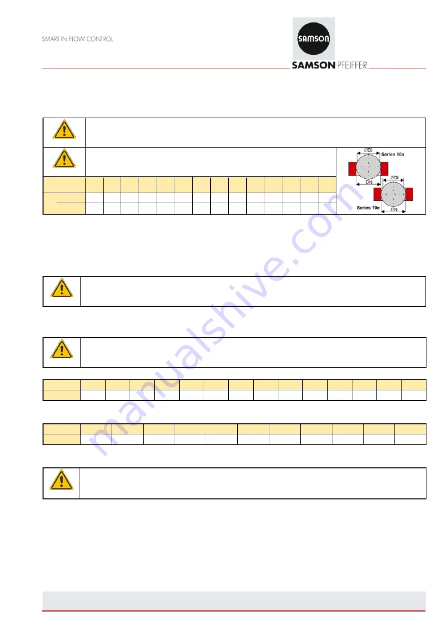
The inside diameter of the mating flanges must leave sufficient room for the 
opened butterfly disc to ensure that it cannot be damaged on swinging out. See 
Table 2. 


DN 

50 

65 

80 

100  125  150  200  250  300  350  400  500  600  800 

Di 

BR10a 

76,5 

126  175  222  274  326  366  465  573  763 

BR10e 

45 

45 

62 

86 

116  140  187  238  282 

390 

Table 2 - Minimum required inside diameter of the mating flanges 


The process medium can flow through the valve in either direction. The preferable mounting position for shut-off butterfly 
valves is with a shaft in a horizontal position. However, if possible, the gear should not be located directly underneath the 
shut-off butterfly valve.  


Make sure the arrow on the valve body corresponds with the direction of flow in the pipeline. 


Note


In special cases, it may be necessary for the valve to be tightly shut against the direction of flow. The installation 
in such special cases must be determined by the operator of the pipeline (e.g. to protect a pump). 


On inserting the valve (and flange gaskets) into a ready mounted pipeline, keep a certain clearance between the pipeline 
ends to ensure that all facings (and gaskets) remain undamaged.  


Caution


Tighten the flange bolts evenly and in a criss-cross pattern in at least three steps. Tighten all flange bolts using the 
torques specified in Tables 2 or 3. 
Use a torque wrench to ensure that the torque specified is reached, yet not exceeded. 


DN [mm] 

50 

65 

80 

100 

125 

150 

200 

250 

300 

350 

400 

500 

600 

800 

MA [Nm] 

45 

45 

65 

75 

55 

140 

170 

140 

170 

170 

240 

240 

310 

480 

Table 3 – Flange torques for DIN-Flanges 


DN [Zoll] 

3“ 

4“ 

6“ 

8“ 

10“ 

12“ 

14“ 

16“ 

20“ 

24“ 

32“ 

MA [Nm] 

65 

50 

100 

150 

140 

160 

160 

230 

240 

300 

470 

Table 4 – Flange torques for ANSI-Flanges 


Warning 

Since PTFE plastic facings have a tendency to creep, we strongly recommend after installation to retighten the 
bolted joint of the valve body using the tightening torques in Table 2 if the valves have been in storage for a long 
time. 


5.  Pressure check in pipeline section 

The pressure check of valves has already been carried out by the manufacturer. To check the pressure of a section of pipeline 
with installed valves, the following points must be observed:  

Содержание Pfeiffer BR 10a Series

Страница 1: ...ed standards EN 593 AD2000 Regulations Product standard for butterfly valves Regulations for pressurized valve body parts Type designation and technical features Pfeiffer data sheets TB10a and TB10e NOTE This Manufacturer s Declaration applies to all valve types listed in this catalogue Applied conformity assessment procedure Conforming to Annex III of the Pressure Equipment Directive 2014 68 EU M...

Страница 2: ...ntended use 3 2 Safety instructions 3 2 1 General safety instructions 3 2 2 Safety instructions for the operator 3 2 3 Particular hazards 4 2 4 Designation of the shut off butterfly valve 5 3 Transport and storage 5 4 Installation in the pipeline 6 4 1 General 6 4 2 Installation instructions 6 5 Pressure check in pipeline section 7 6 Standard operation and maintenance 8 7 Troubleshooting 8 8 Furth...

Страница 3: ...4 34 EU Note Pfeiffer valves do not have their own potential ignition source according to the risk assessment in the rare incident of an operating fault in accordance with DIN EN 13463 1 and therefore do not fall within the scope of the Directive 2014 34 EU Relating to this directive CE marking is not permissible The integration of valves into the equipotential bonding of a plant applies to all me...

Страница 4: ...t once a year Depending on how long the valve remains in one position breakaway and operating torques may differ considerably than those specified in the data sheet Attention For double eccentric valves Make sure that the butterfly disc is always operated within a range of between 0 90 Turning the butterfly valve over 0 leads to irreparable damage to the sealing ring e g sealing strip this must th...

Страница 5: ...rection of flow Note see note in section 4 2 Installation instructions Table 1 Designation of the butterfly valve Keep the labeling on the valve body and on the nameplate to ensure that the valve can be identified at all times 3 Transport and storage Shut off butterfly valves with linings must be carefully handled transported and stored Store the valve with its protective packing and or with its p...

Страница 6: ...gned to be used as step ladders Do not apply any weight load to the gears This can damage or destroy the shut off butterfly valve Warning Gears that weigh more than the shut off butterfly valve Support any gears which due to its size and or mounting situation would otherwise cause the valve to bend under the load 4 2 Installation instructions Note Lined surfaces of the valve must be specially prot...

Страница 7: ...corresponds with the direction of flow in the pipeline Note In special cases it may be necessary for the valve to be tightly shut against the direction of flow The installation in such special cases must be determined by the operator of the pipeline e g to protect a pump On inserting the valve and flange gaskets into a ready mounted pipeline keep a certain clearance between the pipeline ends to en...

Страница 8: ...e shut off butterfly valve from the BR10e Series with an additional packing can be fitted with a leak off connection e g at the valve neck on request This allows you to check whether the packing is leaking If a valve leaks proceed as described in section 7 Troubleshooting 7 Troubleshooting Observe the safety instructions listed in section 2 on troubleshooting Warning To remove a valve from a pipel...

Страница 9: ...ion Only use original parts from Pfeiffer Note 2 If after removing the valve from the pipeline it is found that the PTFE PFA lining is not sufficiently resistant to the process medium select parts made of a suitable material Leak at the shaft If it must be repaired replace the shaft observing section 2 3 Particular hazards Contact Pfeiffer for spare parts and necessary instructions Malfunction If ...

Отзывы: