EB 2520 EN
17
Design and principle of operation
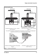
Dimensional drawings
DN 15 to 25
DN 32 to 50
H
ØD
L
H2
min. 150 mm
H
ØD
H2
L
min. 150 mm
Control line connection G ¼, for A = 40, 80,
160 and 320 cm²
Control line connection G ¼, for A = 640 and
1200 cm²
The control line connection is turned by 90° in the drawing. The connection is normally located
opposite the side with the arrow indicating the direction of flow.
G ¼ fitting
Control line connection at the side of the actuator
housing
Control line connection on the bottom of the
actuator housing
Fig. 6:
Dimensions of Type 2405
Содержание 2405 Series
Страница 36: ...36 EB 2520 EN Certificates...


