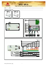
SPU / SPLS
Single Point Unit / Single Point Light & Sound
IS SPU_SPLS 190304 (Sv_Eng)
7
Operation
GB
FUNCTION
When power supply is switched on, a green LED will flash to
indicate
power ”ON”. This will also start the heating process of
the sensor. After approximately 4 minutes the green LED will
light and indicate
”Sensor Active”.
The unit has one yellow and two red LEDs. The yellow LED
indicates low gas concentration
(Alarm C)
and the red LEDs
indicate medium gas concentration
(Alarm B)
and high gas
concentration
(Alarm A)
.
When gas is detected the LEDs
(2)
will light and the relay
corresponding to the alarm level will change state. If alarm delay
is chosen (see below) the respective LED will flash, and it will
light (and the relay will change state) when the chosen delay
time is exceeded.
SPLS
High-intensity LED lights up at B-alarm, buzzer is activated at A-
alarm. The time delay does not apply to sound & light lid.
AUTOMATIC/MANUAL RESET
Is managed by DIP switch
(1)
n
o
3 where “on” means automatic
reset and “off” means manual reset by pressing the “Reset/Test/
Service”-button (located under the cover).
ALARM TIME DELAY (T1)
Is managed by DIP-switches
(1)
n
o
1 and n
o
2:
n
o
1
n
o
2
Delay
on
on
No alarm delay
off
on
1 minute alarm delay
on
off
10 minutes alarm delay
off
off
30 minutes alarm delay
FAIL SAFE
Relays are in normal mode energized and will change state if
power failure or if a fault situation occurs.
SELF TEST FUNCTION
Press the “Reset/Test/Service”-button
(5)
for 5 seconds and the
test program will start and go through all LED functions and all
relay functions in five seconds intervals.
FAULT FUNCTION
If there is a voltage drop (GV-value below 0,1V) from the sensor
there is a fault situation. During the first four hours the green
LED will
go out and the other LED’s will flash. Alarm relay C will
change state.
After four hours the LED “Alarm B” will light (other LED’s will go
off)
and relay “Alarm B” will also change state.
SERVICE FUNCTION
Pressing the ”Reset/Test/Service” button
(5)
for 10 seconds will
lock all alarm functions for 60 minutes. During this period, it is
always possible to start a new 60-minutes period by pressing the
button for 10 seconds again. Return to active status is automatic
at the end of the 60-minutes period or may be done manually by
a single press on the
“Reset/Test/Service”-button. When the
service function is activated all
LED’s will flash and all relays will
be in normal mode position.
NOTE!
The alarm functions in the lid of the SPLS are not
deactivated when the service mode is active.
SOUND, LIGHT & MUTE BUTTON (SPLS only)
”MUTE” button
(9)
mutes the buzzer for 60 minutes. If gas
concentration drops beneath A-level alarm buzzer
(7)
is
deactivated and if gas concentration drops beneath B-level
alarm LED
(8)
is deactivated. More details look on page 2
(10)
.
MANUAL ACTIVATION OF ALL ALARM LEVELS
Closed contact/loop gives full sensor signal resulting in all alarm
levels getting activated
(11)
.
INSTALLATION
The detector is connected to the screw terminals on the main
PCB-board
(6)
. See the wiring diagram
NOTE!
SETTING ALARM LEVELS (THRESHOLDS)
The monitoring unit is delivered as standard with basic set
alarm levels (see page 3).
Alarm levels must be set for chosen gas/detector type
during commissioning.
Settings depend on detector type and are made using the
DT300 service instrument. DT300 is to be plugged in the test
terminal. (3)
(Option) The unit can be delivered with pre-set alarm levels
for specific detector/gas.
Contact us for more information.
MAINTENANCE, ANNUAL CHECK
The monitoring unit should be checked at least twice a year.
A basic function test can be performed using the DT300 service
instrument.
Extended control and calibration require also test gas with a
specific concentration.
Contact us for more information.
TECHNICAL DATA
Housing:
Polycarbonate, PC
Power supply:
SPU230 / SPLS230:
85..230V AC, 50/60Hz
SPU24 / SPLS24:
12..24V AC/DC
Power consumption:
Max 3W
Indications:
Power/Active and alarm indication on
three levels.
Outputs relay:
Potential free contacts (230V, max 5A)
Ambient temp:
-40..50
0
C
Humidity:
0..95% RH (non-condensing)
Glands:
5 x M16 membrane glands
Screw terminals:
< 1,5 mm
2
, fuse < 10A
Dimensions (LxHxD)
160 x 80 x 60 mm
NOTE!
High voltage under the lid!
The unit must only be opened by authorized personnel!
NOTE!
Detectors with semi conductive (SC) sensor head are not
gas specific. Care should be taken when installing the
equipment to minimize any cross contamination from other
gases or vapors.
For further guidance on specific applications contact us.


