background image

6

854 815 R. 12/21

SAMOA Industrial, S.A. · Pol. Ind. Porceyo,  I-14 · Camino del Fontán, 831 · 33392 -  Gijón - Spain · Tel.: +34 985 381 488 · www.samoaindustrial.com

2021_12_16-12:00

EN

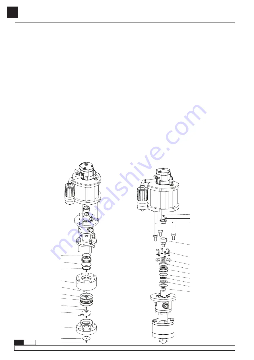
CLEAN OR REPLACE THE FOOT VALVE

ATTENTION:

 on this procedure is necessary lift the pump.


1. 

Fasten the priming rod in lower part (115) and unscrew the nyloc nut (117). Remove the priming valve (116). 

 2. 

Unscrew the bolts (102) and remove the pump from inlet body (105).

 3. 

Remove the inlet body (105) and valve guide (107).

 4.

 Remove the disc valve (110). Examine the valve (110), the U-seat in foot valve (114) and priming rod (115) for any damage. Replace if it’s necessary.

 5. 

Replace the O-rings (108), back-up rings (109). Fit a new O-ring (71, 83) and compressible spacer (104). 

 6.

 Assembly the foot valve following this section, reversing each step. Apply Loctite 243 on thread (102).


 It is also available a whole foot valve kit (754955) with all components in disk valve assembled.

CLEAN OR REPLACE THE PACKING NUT


1.

  Using the air motor, stop the pump in the lower down stroke. Release the pump pressure.

 2.

 Remove the bolt (63) and unscrew the nut (64).


3.

 Using air motor, raire gently the air motor rod (47) until upper upstroke. Close the air.


4.

 Remove the coupling (67), the bolts (68) and gland top plate (70).


5.

 Fit two M5 bolts in the bearing (72) and pull out. The u-seal (73) should be stayed with the packing nut, if it stayed in the pump, slide it up 

the packing rod (91) gently until is free.

 6.

 Examine the packing nut (72) and the rod (91) for wear and or damage as if they are defective any new packing rod seal will fail. If the nut 

is faulty this will replaced now, but if the rod is faulty the pump will have to be completely dismantled (please, follow the section clean and 
replace piston valve).


7.

 Fit a new o-seal (71). Replace the packing rod seal (73) to the packing nut (72), lightly greasing the seals to aid assembly.


8.

 Push the nut (72) and seal over the packing rod (91) until the U-seal stop (74). Apply Loctite 243 on thread (67, 68). Assemble the pump 

following this section, reversing each step.

REPAIR AND CLEANING PROCEDURE

Fig. 10

47
63
64

67

68

70
71
72
71
73
74
91

Fig. 9

102

71

83

104

105

115

106
107

108
109
110

114

116
117

Содержание PM100

Страница 1: ...ical service guide Gu a de servicio t cnico y recambio Guide d instructions et pi ces de rechange Service und Ersatzteilhandbuch Part No C d R f Art Nr 545 010 545 010 000 22 1 RATIO AIR OPERATED INK...

Страница 2: ...pectedly This unit may have stored pressure released all pressure and disconnect from any fluid systems before servicing To ensure safe operation of this unit all service work should be by qualified p...

Страница 3: ...h the ink outlet is closed There is a ink leakage at some point in the circuit Verify and tighten or repair Contamination in the piston valve 92 Disassemble and clean Replace if damaged 92 Contaminati...

Страница 4: ...s seals factory installed kit 539006 This is strongly recommended in order to ensure the correct assembly of the seals LIFTING THE PUMP ATTENTION This pump is extremely heavy A lifter is neccesary in...

Страница 5: ...nd split the motor 13 from the flange 34 Take away the washer 29 and replace the seal 8 8 Take away the cylinder 48 while carefully holding the air piston 41 9 Remove the pin 65 from male coupling 66...

Страница 6: ...the pump in the lower down stroke Release the pump pressure 2 Remove the bolt 63 and unscrew the nut 64 3 Using air motor raire gently the air motor rod 47 until upper upstroke Close the air 4 Remove...

Страница 7: ...emove cylinder assembly 100 4 Unscrew two grub screw 97 and remove the piston 98 5 Remove the piston guide 99 circlip 94 the ring 95 and the U seal 96 Replace the U seal 96 It is recommend that after...

Страница 8: ...te Este equipo puede contener presi n almacenada elimine la presi n y desconecte la bomba del sistema de entrada y salida de fluidos en caso de realizar cualquier mantenimiento Para asegurar el correc...

Страница 9: ...lene el dep sito La bomba sigue funcionando aunque se cierre la salida de tinta Existe fuga de tinta en alg n punto del circuito Verifique y apriete o repare V lvula de impulsi n 92 no cierra por impu...

Страница 10: ...ya instaladas de f brica kit 539006 sta es la opci n recomendada para asegurar que las juntas est n correctamente instaladas IZADO DE LA BOMBA ATENCI N este equipo es extremadamente pesado Es necesar...

Страница 11: ...los cinco tornillos 35 y separe el cuerpo motor 13 de la brida 34 Extraiga la arandela 29 y sustituya la junta 8 8 Retire el cilindro 48 sujetando con cuidado el mbolo 41 9 Extraiga el pasador 65 del...

Страница 12: ...or de aire detenga la bomba en la posici n inferior de la carrera Libera la presi n que pudiera tener la bomba 2 Retire el tornillo 63 y desenrosque la tuerca 64 3 Con ayuda del motor de aire suba sua...

Страница 13: ...4 Desatornille los tornillos prisioneros 97 y extraiga el pist n 98 5 Quite el aro de gu a 99 Retire el anillo de retenci n 94 y extraiga el anillo 95 y el collar n 96 Sustituya el aro gu a 99 y el c...

Страница 14: ...yaux les vannes et autres raccords Cet quipement peut contenir une pression stock e supprimer la pression et d connecter la pompe du syst me d entr e et de sortie de fluide en cas de maintenance Pour...

Страница 15: ...r servoir La pompe continue de fonctionner m me si la sortie d encre est ferm e Il y a une fuite d encre quelque part dans le circuit V rifiez et serrez ou r parez La soupape de d charge 92 ne se ferm...

Страница 16: ...mont s en usine kit 539006 Ceci est fortement recommand pour s assurer que les joints sont correctement install s LEVAGE DE LA POMPE ATTENTION cet quipement est extr mement lourd Certains quipements d...

Страница 17: ...cinq vis 35 et s parer le corps du moteur 13 de la bride 34 Retirez la rondelle 29 et remplacez le joint 8 8 Retirer le cylindre 48 en tenant soigneusement le piston 41 9 Retirez la goupille 65 de l a...

Страница 18: ...pe en position basse de course Rel chez toute pression que la pompe pourrait avoir 2 Retirer la vis 63 et d visser l crou 64 3 A l aide du moteur pneumatique soulever doucement la tige de piston 47 ju...

Страница 19: ...de r glage 97 et retirer le piston 98 5 Retirez la bague de guidage 99 Enlever la bague de retenue 94 et retirer la bague 95 et le collier 96 Remettre en place la bague de guidage 99 et le collier 96...

Страница 20: ...heftig und unerwartet bewegen Dieses Ger t kann gespeicherten Druck enthalten den Druck entlasten und die Pumpe im Falle von Wartungsarbeiten vom Materialeinlass und auslasssystem trennen Um den korre...

Страница 21: ...bei geschlossenem Tintenauslass weiter Irgendwo im Kreislauf tritt Tinte aus Pr fen und festziehen oder reparieren Impulsventil 92 schlie t aufgrund von Verunreinigungen nicht Ausbauen und reinigen 92...

Страница 22: ...itig eingebauten Dichtungen Satz 539006 Dies ist die empfohlene Option um sicherzustellen dass die Dichtungen richtig installiert sind HEBEN DER PUMPE ACHTUNG Dieses Ger t ist extrem schwer Einige Heb...

Страница 23: ...ie die f nf Schrauben 35 und trennen Sie das Motorgeh use 13 vom Flansch 34 Entfernen Sie die Unterlegscheibe 29 und ersetzen Sie die Dichtung 8 8 Entfernen Sie den Zylinder 48 indem Sie den Kolben 41...

Страница 24: ...en Sie den eventuell vorhandenen Druck der Pumpe ab 2 Entfernen Sie die Schraube 63 und l sen Sie die Mutter 64 3 Heben Sie den Vorbau 47 mit dem Luftmotor vorsichtig in die obere Hubposition Mach die...

Страница 25: ...en 97 und entfernen Sie den Kolben 98 5 Entfernen Sie den F hrungsring 99 Haltering 94 entfernen und Ring 95 und Bund 96 entfernen F hrungsring 99 und Bund 96 ersetzen Nach einer gr ndlichen Reinigung...

Страница 26: ...853602 Motor washer Arandela motor 1 30 946054 O ring Junta t rica 4 31 946018 O ring Junta t rica 1 32 853500 Motor seal Junta conformada motor 1 33 950701 Eye bolt C ncamo 2 34 754104 Upper flange...

Страница 27: ...a metalopl stica 1 81 945724 Hex nipple Racor 1 82 854418 Adaptor ring Adaptador cilindro 1 83 946893 O ring Junta t rica 2 84 945590 Hex nipple Racor 1 85 945563 Elbow Codo 1 86 950326 Bleed valve V...

Страница 28: ...Joint torique O Ring 4 31 946018 Joint torique O Ring 1 32 853500 Joint conform de moteur Geformte Motordichtung 1 33 950701 Boulon il Ringschraube 2 34 754104 Collier sup rieure Oberer Flansch 1 35 9...

Страница 29: ...ssnippel 1 82 854418 Adaptateur de cylindre Zylinderadapter 1 83 946893 Joint torique O Ring 2 84 945590 Raccord hexagonal Anschlussnippel 1 85 945563 Coude Kr mmer 1 86 950326 Vanne de purge Entl ftu...

Страница 30: ...ameter Di metro pist n de aire Diam tre du piston d air Durchmesser des Luftkolbens 250 10 Air piston stroke Recorrido del pist n de aire Course du piston pneumatique Luftkolbenhub 100 mm 4 Weight Pes...

Страница 31: ...38 39 40 41 40 42 43 44 45 46 47 48 49 50 49 51 52 53 36 55 56 57 58 59 60 61 62 63 64 65 66 67 68 69 70 71 72 71 73 74 71 75 76 77 78 79 80 81 82 83 84 85 86 87 88 89 55 90 91 92 93 94 95 96 97 98 99...

Страница 32: ...Porceyo I 14 Camino del Font n 831 33392 Gij n Spain declares that this product 545 010 545 010 000 conforms with the EU Directive 2006 42 EC SAMOA INDUSTRIAL S A Pol Ind Porceyo I 14 Camino del Font...

Отзывы: