


www.larius.com
13
GHIBLI 30:1/40:1
REV.
. 01 - 03/2020 - Cod. 150088
L
M
3 mm
M1
M2
M3
M4
M5
M6
L1
L2
M7
M7
M6
M8
M3
M3
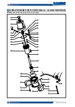
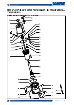
DISASSEMBLY OF THE
PNEUMATIC MOTOR
• Close the compressed air supply to the pump and release
the residual pressure in the plant.
• Unscrew the motor cap
(M1)
and pull it upwards together
with the guide rod
(M2)
.
•
Hold the guide rod
(M2)
a
nd remove the plug
(M1)
(using
two wrenches).
•
Remove the screws
(M4)
and the washers
(M5).
• Carefully extract the motor cylinder
(M6)
fom the pump.
MANUAL RESET OF THE
PNEUMATIC MOTOR
• The feed air pressure of the pump must never be higher than
the maximum value indicated in the technical data. Exceed
this value can block the valves of the pneumatic motor in
the intermediate position of the cycle reversal.
• To start again a blocked motor, close the air supply and
release pressure in the plant. This operation should allow
the recovery of the valves.
• In case the motor is blocked, proceed as follows:
- Close the air supply to the pump and release the residual
pressure in the plant;
- unscrew the motor cap
(L1)
and pull it upward along with the
guide rod
(L2)
so as to manually trigger the stroke inversion
unit;
- screw again the plug.
• Check the condition of each part of the motor.
• For any eventual replacement of the screws
(M7)
of the
traverse
(M8)
, for their reassembly and correct adjustment.
Replace immediately the plug
(M1)
with a usual
M8
(M3)
nut before the guide rod slides into the
cylinder.
Fig. 1M
Fig. 1L
Fig. 2M