


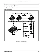
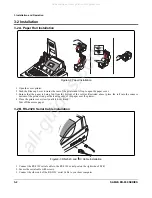


2 Product Specifications
2-4
SAM4S ER-650 SERIES
2-3 Thermal Printer Specifications
2-3 A. Printer Specification
Item Description
Remark
Model
•
STM-210
Print Method
•
Thermal Line Printing
Total number of dots
•
384 Dots / I Line
Printing Format
Dot Pitch
•
Vertical
: 0.125 mm
•
Horizontal
: 0.125 mm
Printing Speed
•
50 mm/s ( At 8.5V of Motor Terminal Voltage)
Printing Direction
•
Unidirection with friction feed
Feeding Method
•
Friction Feed
Minimum Feed Pitch
•
0.0625 mm
Paper Feeding
Feeding Speed
•
50 mm/s (At 8.5V of Motor Terminal Voltage)
Power Voltage
•
8V / 8.5V (Recommend)
Head/Motor
Power Supply Volt
Circuit input Voltage
•
5V
Head Control/Sensor
Heat Element Density
•
8 Dots/mm (0.125 mm/Dot)
Total Head Elements
•
384 Dots/Dot Line
Available Printing Width
•
48 mm
Printer Head
Heat element typical
Ω
•
176
Ω±
4%
Motor
Paper Feed Motor
•
4-Phase Bi-Polar Stepping Motor
Head Temperature
•
Thermister
Paper-End Sensor
•
Reflecting Photo Sensor
Sensor
Cover Open Sensor
•
Micro Switch
Life
•
15,000,000 Lines
Reliability
MCBF
•
37,000,000 Line
Dimension (mm)
•
82.5 (W)
×
147.3 (D)
×
101.4 (H)
Weight
•
Approx. 365 g
Table2-2 Thermal Printer Specifications
All manuals and user guides at all-guides.com
all-guides.com
Содержание ER-650
Страница 2: ...All manuals and user guides at all guides com...
Страница 27: ...3 Installation and Operation 3 8 SAM4S ER 650 SERIES Memo All manuals and user guides at all guides com...
Страница 48: ...SAM4S ER 650 SERIES 7 1 7 PBA Layout and Part List 7 1 Main PBA All manuals and user guides at all guides com...
Страница 68: ...9 Block Diagram 9 2 SAM4S ER 650 SERIES Memo All manuals and user guides at all guides com...
Страница 70: ...10 Wiring Diagram 10 2 SAM4S ER 650 SERIES Memo All manuals and user guides at all guides com...
Страница 73: ...SAM4S ER 650 SERIES 11 3 11 2 MEMORY PART All manuals and user guides at all guides com...
Страница 75: ...SAM4S ER 650 SERIES 11 5 11 4 FISCAL PART All manuals and user guides at all guides com...
Страница 77: ...SAM4S ER 650 SERIES 11 7 11 6 DRAWER DISPLAY VFD PART G G All manuals and user guides at all guides com...
Страница 78: ...11 8 SAM4S ER 650 SERIES 11 7 KEY SCAN PART Y All manuals and user guides at all guides com...
Страница 79: ...SAM4S ER 650 SERIES 11 9 11 8 LCD DISPLAY PART All manuals and user guides at all guides com...
Страница 80: ...11 10 SAM4S ER 650 SERIES 11 9 PRINTER PART G G All manuals and user guides at all guides com...
Страница 86: ...All manuals and user guides at all guides com a l l g u i d e s c o m...


