background image


    Shin Heung Precision. May 2004   

                     Printed in KOREA   

                                                          V1.0 

                                                          Code No. : JK68-60958A


Содержание ER-420 Series

Страница 1: ...on Statements 2 Product Specifications 3 Installation and Operation 4 Disassembly and Assembly 5 Maintenance and Adjustment 6 Exploded Views and Parts List 7 PCB Layout and Parts List 8 Troubleshootin...

Страница 2: ......

Страница 3: ...Electronic Cash Register Notes Notes may appear anywhere in the manual They describe additional information about the item Precaution symbols Indicates a Safety Precaution that applies to this part co...

Страница 4: ...may not in whole or in part be copied photocopied reproduced translated or converted to any electronic or machine readable from without prior written permission of Shin Heung Precision SAM4S ER 420M...

Страница 5: ...is subject to change without prior notice Therefore you must check the correspondence of your manual with your machine No part of this manual may be copied or reproduced in any form or by any means w...

Страница 6: ...edges and especially the AC and high voltage supplies Always inspect for pinched out of place or frayed wiring Do not change the spacing between comp onents and the printed circuit board Check the AC...

Страница 7: ...nstrument s ground lead to the instrument chassis ground before connecting the positive lead always remove the instrument s ground lead last 1 3 Precautions for Electrostatic Sensitive Devices ESDs 1...

Страница 8: ...ta Storage 60 Days When battery is Full charged Interface Serial RS 232C Flow Control DTR DSR H W Flow Control XON XOFF S W Flow Control Baud Rate 1200 2400 4800 9600 19200 Bps Connector DB9P Female I...

Страница 9: ...ONI C CAS H REG IST ER 400 450 266 Figure2 1 Dimensions 2 2 B Location Feature ER 420 EL EC TR ON IC CA SH RE GI ST ER 1 2 3 4 6 7 5 Figure2 2 Location Feature Printer Cover Key Board Drawer Customer...

Страница 10: ...d Minimum Feed Pitch 0 125 mm Paper Feeding Feeding Speed 75 mm Sec 20 Line sec Power Voltage 24 0V Recommend Head Motor Power Supply Volt Circuit Input Voltage 5V Head Control Sensor Heat Element Den...

Страница 11: ...ecification The following paper should be used for good print quality and stable paper feeding Item Description Remark Paper Type standard Han sol x Paper HPK 110 Single ply Thermal Paper Roll Han sol...

Страница 12: ...the printing layout taking this into account 2 4 Power Specification Item Description Remark Input Voltage Current U S A AC 120V 60Hz 0 3A Min 102V Max 138V Europe AC 230V 50Hz 0 16A Min 195 5V Max 26...

Страница 13: ...G F C N 1 E L A M E F 6 3 D X R 2 G S 5 C N 8 C P N I P 9 E D I S t r o h S n i P 8 6 n i P 7 4 R S D 6 C N 7 D X T 3 R T D 4 E L A M G F C N 1 E L A M D B N O R C E E L A M E F R O T C E N N O C D X...

Страница 14: ...urce The Supply Current 200mA is total value including COM1 and COM2 Power Consumption If the Total Power Consumption of the attached devices is exceeded the specification 200mA the system stops the V...

Страница 15: ...ERIES 2 5 B EKLZ Interface 2 5 B a Cable Connection CN9 EKLZ Signal Pin No Wire Color Pin No Signal VCC 1 RED 6 VCC TXD 2 YELLOW 3 RXD RXD 3 GREEN 1 TXD 4 GND 5 BLACK 7 GND Table2 13 EKLZ Cable Connec...

Страница 16: ...SAM4S ER 420M F SERIES 3 1 3 Installation and Operation 3 1 System Configuration ER 4 20 ELE CTR ONI C CAS H REG IST ER Figure 3 1 System Configuration...

Страница 17: ...PH and Platen Roller Return the LEVER LOCK Figure 3 2 3 5 Tear the end of the paper on the left at the receipt printer like the shown figure Figure 3 2 4 6 Push the button for paper feed on the keyboa...

Страница 18: ...crews 3 Connector the other end of the RS 232C serial Cable to your host computer Figure 3 3 Cable Installation 3 2 C Options No Item Description Remark 1 Water Proof 2 Dust Cover 3 Memory SRAM 4MBITs...

Страница 19: ...ng key lock positions Mode Accessible Position Remark VOID Void Off Register Manager X Off Register Manager Z Off Register Manager Clear Totals PGM Void Off Register Manager Clear Totals Program S Voi...

Страница 20: ...d 48Key 3 3 C Initial Clear 1 Turn off the power switch 2 Turn the mode switch marked P to P MODE 3 Hold down the SBTL key on the keyboard and turn on the power switch at the same time Figure3 6 Initi...

Страница 21: ...ode painting part Service Mode spins the Mode Key once just in a Program Mode to the right direction And need C Key to execute a Service Mode 1 Turn off the power switch 2 Turn the Mode switch to Serv...

Страница 22: ...ard 3 The key code of pressed key will be showed on the VFD 4 Turn the mode switch to any position to finish this test 3 3 E d Test Mode Switch 1 Press Press 1 3 and SBTL key on key board 2 Turn the m...

Страница 23: ...3 Installation and Operation 3 8 SAM4S ER 420M F SERIES MEMO...

Страница 24: ...Y CASE UPPER B Page9 4 4 Remove the four screws B 17 from the PMO HOLDER DISPLAY B 14 Page9 4 5 Separate the LCD B 16 from the PMO HOLDER DISPLAY B 14 Page9 4 6 Separate the harness from the LCD B 16...

Страница 25: ...3 E 4 and remove the three screws E 2 Lift up the PBA MAIN BOARD E 8 page9 11 2 Separate the harness and lift up the ASS Y FISCAL BOARD E 6 from the PMO CASE LOWER E 18 page9 11 3 Separate the harness...

Страница 26: ...the printer HEAD TIP LEVER LOCK Figure 5 1 Clean the Printer Head Caution Note that the thermal head Thermal Element and Radiation Plate becomes very hot during normal operation To prevent the danger...

Страница 27: ...5 Maintenance and Adjustment 5 2 SAM4S ER 420M F SERIES MEMO...

Страница 28: ...SAM4S ER 420M F SERIES 6 1 6 Exploded Views and Parts List 6 1 Exploded View ER 420M Figure 6 1 Total Disassembly ER 420M...

Страница 29: ...6 Exploded Views and Parts List 6 2 SAM4S ER 420M F SERIES 6 1 Exploded View ER 420F Figure 6 2 Total Disassembly ER 420F...

Страница 30: ...ER PRINTER A ASS Y COVER PRINTER No Parts No Description Specification Q ty Design Location Serviceable Remark A JK97 20017A MEA COVER PRINTER 1 Y A 1 JK72 20087A PMO WINDOW JOURNAL 1 Y A 2 JK72 20086...

Страница 31: ...A IPR BRKT MODE_S W 1 Y B 5 6002 000319 SCREW TAPPING PH 2 M3 L8 ZPC YEL 2 Y B 6 6002 000172 SCREW TAPPING PH 2S M4 L15 1 Y B 7 JK96 10044A MODE KEY ASSY 1 Y B 8 JK72 40209B PMO WINDOW TURRET 1 Y B 9...

Страница 32: ...DE_S W 1 Y B 5 6002 000319 SCREW TAPPING PH 2 M3 L8 ZPC YEL 2 Y B 6 6002 000172 SCREW TAPPING PH 2S M4 L15 1 Y B 7 JK96 10044A MODE KEY ASSY 1 Y B 8 JK72 40209B PMO WINDOW TURRET 1 Y B 9 JK92 01231A P...

Страница 33: ...14 C 5 13 C 5 17 C 5 22 C 5 3 C 5 5 C 5 7 C 5 8 C 5 9 C 5 11 C 5 10 C 5 12 C 5 15 C 5 14 C 5 18 C 5 24 C 5 16 C 5 19 C 5 23 C 5 21 C 5 6 C 5 2 C 6 C 7 C 8 C 5 22 2 C 5 22 1 C 5 22 3 C 5 C 5 20 C 1 C...

Страница 34: ...6 Exploded Views and Parts List SAM4S ER 420M F SERIES 6 7 Figure 6 7 Lubrication Points of the Printer STM 320...

Страница 35: ...STM 320 1 N C 5 3 3 JK72 20077A PMO GEAR ROLLER_43 STM 320 1 N C 5 3 4 JK72 20078A PMO PULLEY SMALL STM 320 1 Y C 5 3 5 JK70 50004A POLY WASHER ID 2 8 OD 6 0 T0 5 RED 1 Y C 5 4 JK72 20074A PMO LEVER...

Страница 36: ...6 Exploded Views and Parts List SAM4S ER 420M F SERIES 6 9 6 2 D ASS Y KBD 48KEY RAISED Figure 6 8 ASS Y KEYBOARD 48 Key...

Страница 37: ...5 JK81 10946A KEY CAP L 1X2 1 Y D 6 JK81 20014A KEY TOP ASS Y L 1X2 1 Y D 7 JK81 20001A SPRING RETURN 1X2 2 Y JK81 10933A KEY TOP 1 1 Y JK81 10934A KEY TOP 2 1 Y JK81 10935A KEY TOP 3 1 Y JK81 10936A...

Страница 38: ...6 Exploded Views and Parts List SAM4S ER 420M F SERIES 6 11 6 2 E ASS Y CASE LOWER C y y E 26 C 8 C 8 Figure 6 9 ASS Y CASE LOWER...

Страница 39: ...120V 60Hz 1 Y E 10 JK26 00014A TRANS POWER EUROPE 230V 50Hz 1 Y E 11 6002 000175 SCREW TAPPING PWH 2 M3 L8 ZPC YEL 2 Y E 12 JK92 01227B PBA SUB POWER SW 1 Y E 13 JK60 00001A SCREW ASSYTAPTITE M3 L8 3...

Страница 40: ...6 10 ASS Y DRAWER 4B 8C b2 b1 b11 b12 b5 b3 b4 b7 b8 b6 b9 c ASS Y HOUSING e ASS Y BOTTOM d ASS Y LOCK b ASS Y TRAY TILL b10 e1 e5 e2 e3 e4 e7 e6 e8 d1 d2 d3 d4 d11 d6 d7 d9 d10 d5 d8 c2 c1 c3 a8 a4 a...

Страница 41: ...MEA UNIT BILL COIN A TYPE 7B8C 1 Y a 1 6002 000175 SCREW TAPPING PWH 2 M3 L8 ZPC YEL 3 Y a 2 JK70 00068A IPR HOLDER PLATE A TYPE 1 Y a 3 JK72 00083A PMO BILL PARTITION A TYPE 5 Y a 4 JK72 00082A PMO...

Страница 42: ...TCH LONG LEVER 1 N d 4 JK75 00027B MEC LOCK LEVER A TYPE 2 LATCH SHORT LEVER 1 N d 5 6107 001041 SPRING ES 0 4 D4 8 L18 1 Y d 6 JK33 10500A SOLENOID DC A DRAWER 1 Y d 7 6001 000131 SCREW MACHINE BH 2...

Страница 43: ...6 Exploded Views and Parts List 6 16 SAM4S ER 420M F SERIES MEMO...

Страница 44: ...SAM4S ER 420M F SERIES 7 1 7 PCB Layout and Parts List 7 1 Main PCB Layout...

Страница 45: ...R27 Y 2001 001292 R CARBON 0 5OHM 1 2W 1 R38 R39 R66 R67 Y 2005 001001 R WIRE WOUND 0 1ohm 5 1W AA TP 3 3x9mm 1 R19 Y 2301 000010 C FILM PEF 100nF 5 100V TP 11 5x12 5mm 1 C5 Y 2401 000032 C AL 100uF 2...

Страница 46: ...2A NPN 350MW SOT 1 Q2 Q3 Q9 Q13 Q14 Q17 Q18 Y 0501 000457 TR SMALL SIGNAL MMBT2222A NPN 350MW SOT Q20 Q21 Y ER420F ONLY 0801 000523 IC CMOS LOGIC 74HCT541 BUFFER DRIVER SOP 1 U17 Y 0801 000523 IC CMOS...

Страница 47: ...R112 R122 R123 R124 R125 R140 Y 2007 000931 R CHIP 470OHM 5 1 10W DA TP 2012 1 R14 R37 R114 R118 R126 R130 Y 2007 001039 R CHIP 56KOHM 5 1 10W DA TP 2012 1 R53 R54 R74 R75 Y 2007 001071 R CHIP 6 8KOH...

Страница 48: ...2 5mm STRAIGHT 1 CN3 Y 3711 004105 WAFER BOX HEADER 1R 4P 2 5mm STRAIGHT 1 CN4 Y 3711 002003 CONN HEADER 16P 2R 2mm ST BLK YDW200 16 1 CN5 Y 3711 000840 CONNECTOR HEADER BOX 30P 2R 2MM STRAIGHT 1 CN1...

Страница 49: ...B Layout No Part No Description Specification Q TY Design Location Serviceable Remark s 3711 000190 CONNECTOR HEADER 1WALL 2P 1R 7 92mm STRA 1 CN3 Y 3711 000829 CONNECTOR HEADER BOX 2P 1R 6 2mm STRAIG...

Страница 50: ...2R 2mm STRAIGHT S 1 CN2 Y JK07 00005A DISPLAY VFD DC10G FUTABA 10 LT 50GK 1 V1 Y JK39 40600A HARNESS DISPLAY ER 380 8P 350mm CORE 1 HARNESS Y JK73 10207A RPR PAD ER 220N SPONGE BLK 2 T5 0 Y 1003 00138...

Страница 51: ...TABA VFD 10 DIGIT Y 7 4 C ER 420M Rear Display VFD 10Digit No Part No Description Specification Q TY Design Location Serviceable Remarks JK92 00970B PBA SUB TURRET ER 450 WORLD BASIC 1 Y 3711 004109 W...

Страница 52: ...X5 1 Y Memory Size 1MBITs No Part No Description Specification Q TY Design Location Serviceable Remark s JK92 00132B PBA SUB FISCAL B D 1MBITs 1 1MBITs ASSY Y 1102 000109 IC EPROM 27C010 128Kx8BIT DIP...

Страница 53: ...221 R CHIP 1 2KOHM 5 1 10W DA TP 2012 1 R4 Y 2007 000872 R CHIP 4 7KOHM 5 1 10W DA TP 2012 10 R1 R5 R13 Y 2203 000192 C CERAMIC CHIP 100nF 80 20 50V Y5V TP 1 C2 Y 0404 001051 DIODE SCHOTTKY SK14 40V 1...

Страница 54: ...Main PBA 2 Check the Bridge Diode BD1 on Main PBA 3 Check the VDRV signal whether it is short 1 Check the Bridge Diode D2 3 4 6 on Main PBA 2 Check the VDISP signal whether it is short N N Power 24V...

Страница 55: ...e LM393 U26 2 Check the Power 24V 5V 3 Check the related Circuit and Pattern on PCB N N SRAM Ok Y Y N CPU Ok Y N 1 Check the nCS nRD nWR signal of SRAM 2 Check the VBT Battery Volt 3 Check the Decoder...

Страница 56: ...the DATA Signal CPU P9 6 3 Check the LATCH Signal CPU P9 7 4 Check the Harness Disconnect Ok Power VDISP VCC Ok Y 1 Refer to the Power Problem 2 Check the Harness 1 Check the Harness 2 Check the VFD...

Страница 57: ...uit and Pattern of 74HC14 U9 2 Check the Harness 3 Check the Sensor of Print Connection PBA Y Line Feed OK N 1 Check the Phase Signal CPU P10 5 P10 6 P7 6 P7 7 2 Check the Driver TEA3718S U7 U8 U12 U1...

Страница 58: ...Check the related Circuit and Pattern 4 Check Change Key Board Assy 5 Check the KBD Connector on PBA Specific Key Failure 1 Check the affected Key 2 Check the Matrix Bus Data Bus 3 Check the Diodes D...

Страница 59: ...Check the Drawer Connector Harness 2 Check the related circuit Component KSD288 Q1 MMBT2222A Q2 on Main PBA 3 Check the Solenoid in the Drawer Compulsory Failure 1 Check the Compulsory Harness Connec...

Страница 60: ...Connector 3 Check the TXD RXD Pin on CPU 4 Check the MAX232 Driving Chip and related Circuit on MAIN PBA Communication Failure 1 Check the connection of the RS 232C and Other side 2 Check the I F Cabl...

Страница 61: ...8 Troubleshooting 8 8 SAM4S ER 420M F SERIES MEMO...

Страница 62: ...ONT LCD POWER CIRCUIT 24V VCC 5 0V VBT 3 6V CHARGE TX RX DTR DSR 3 TR REIVER MAX232 3 SERIAL I F PBA nRESET M51953 4B 8C 5B 5C VSERIAL 5V 200mA KEY DECOD 74HC138 KEY BUFFER 74HC541 KEY BOARD 48 KEY MO...

Страница 63: ...UIT 24V VCC 5 0V VBT 3 6V CHARGE TX RX DTR DSR 3 TR REIVER MAX232 3 SERIAL I F PBA nRESET M51953 4B 8C 5B 5C VSERIAL 5V 200mA KEY DECOD 74HC138 KEY BUFFER 74HC541 KEY BOARD 48 KEY MODE KEY nCS KEY nCS...

Страница 64: ...ption 1 VDISP 30VDC VFD Grid Anode Driving Voltage 2 24 24VDC Cash Drawer Solenoid Driving Fiscal Writing Voltage 3 VCC 5VDC Logic IC Driving VFD Filament Voltage 4 VBT Min 3 6VDC Battery Voltage Use...

Страница 65: ...9 Block Diagram 9 4 SAM4S ER 420M F SERIES MEMO...

Страница 66: ...TPH CLOCK CN2 Drawer 10 FA0 11 TPH STROBE 2 No Signal Name 11 CS_FISCAL EPROM 12 TPH DATA 1 GND 12 FA15 13 GND 2 SEN_DWRCOMP 13 GND 14 JOURNAL LF MOTOR OUT A 3 DRAWER 14 FA14 15 TPH STROBE 1 4 VDRV 15...

Страница 67: ...10 Wiring Diagram 10 2 SAM4S ER 420M F SERIES MEMO...

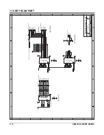
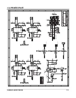
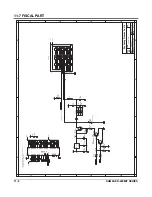
Страница 68: ...In Out Serial I F Block 11 5 5 Key Scan Block 11 6 6 Printer Block 11 7 7 Fiscal I F Block 11 8 8 Power Block 11 9 2 Power Switch PCB Schematics 11 10 3 Display PCB Schematics 1 VFD Front Schematics...

Страница 69: ...FSOUT U10 IC SSCG FS781 SOP8P 2 N C 3 GND 5 OUT 1 VCC 4 DELAY M51953B U25 R108 10K 100nF C59 100pF C76 100nF C74 VCC N ot e B Y TE 8Pi n H 8B i t s D at a B us R O M Fet ch R eset S el ect L 16B i t s...

Страница 70: ...54MM ST CN12 A 100nF C87 VCC D 0 7 VBT 100nF C42 0xC40000 0xC5FFFF 5 4 6 74HC08 U6 B RTC_SDA 100nF C90 100nF C89 R101 4 7K VBT 100nF C85 VBT 100nF C88 Hyun Oh Yun VBT 100nF C50 11 WE 27 VSS2 26 CE 10...

Страница 71: ...F C102 VCC R134 4 7K 2004 04 21 6 CN6 6 3 CN6 3 3 CN2 3 VCC VCC V1 4 R44 10K SK14 D11 2 3 1 Q16 KSA1182 Y D12 SK14 1 CON BOX 22P 2MM 2R ST CN5 A R1 10K C41 100nF M4 D1 1 CN6 1 CON BOX 8P 2 5MM ST YH 5...

Страница 72: ...Y Q 7 R 25 10K U AR T PAR T 2004 04 21 VC C 5 C N 4 5 4 C N 4 4 2 C N 4 2 V1 4 1uF C 22 1uF C 8 VC C 1uF C 17 1uF C 38 L10 R 31 1K VO LT_O N O FF FR O M P_FAI L D SR 2_I N TXD 2_O U T D TR 2_O U T R X...

Страница 73: ...VCC 100nF C100 VCC MODESCAN_COMMON 2 CN16 B 2004 04 21 Key Return 4 CN15 D 7 CN13 7 4 CN13 4 V1 4 VCC 1 CN14 A CON FPC 8P 2 54MM ST 100nF C82 VCC VCC R110 4 7K R111 4 7K R112 4 7K R140 4 7K R113 39 M...

Страница 74: ...60 100 RLFMOT_IN1 RLFMOT_PHB RLFMOT_VREF RLFMOT_PHA RLFMOT_IN0 RLFMOT_VREF 24V NEW SENSOR PCB DESIGN PEND_IN_R JLFMOT_VREF LF 220 mA RLFMOTOUT_B 29 CN7 AC RLFMOTOUT_A RLFMOTOUT_A 25 CN7 Y 23 CN7 W JL...

Страница 75: ...CC 2 3 1 MMBT2222A Q21 D21 MMBD6050LT1 4 7K R131 VCC SK14 D17 VFIS_ONOFF RESET FD 0 7 CS_FISCAL8255 _WR _RD A 1 A 0 D 2 D 1 D 0 D 5 D 4 D 3 D 7 D 6 FA 0 17 Note 8255 RESET Pin is HIGH Active 18 4mA Fi...

Страница 76: ...2004 04 21 V1 4 24V HEATSINK_S HS2 4700uF C1 50V 100uF C21 50V L4 140uH L2 BFD3565R2 R21 3 3K VCC 1 3 2 KSA708 Y Q6 100nF C10 R12 1K M4 D3 M4 D6 2 CN1 B VREF 1 23V 6 N C 4 PWRGND 1 FB 3 ON 5 VIN 7 OU...

Страница 77: ...Drawn by Sheet C TITLE D C D File Name A3 Rev Shin Heung Precision Co Ltd 2 1 1 1 RED BLUE BLUE 9 2 2 RED EARTH BROWN BLUE 1 3 4 ER420 MAIN SCH ER 420 MAIN 9 V125 2 TO MAIN PBA POWER 2004 04 21 V1 4...

Страница 78: ...ER 380 Vf 3 79V I f m A P2_B P8_D P P5_C VD I S Vbc 28 4V I bc 24m A O LD PC B I N FO R JK41 10005A V2 2 2001 03 21 AR R AY 4 VFD _STO R BE VFD _LATC H VFD _SC LK VFD _SD I N ER 350 D I SPLAY 10G N ot...

Страница 79: ...ISPDISCON G4 G3 G1 G2 G3 VF1 4 CN1 D 7 CN1 G 10 CN1 J 3 CN2 C 6 CN2 F 9 CN2 I P8 com f P1 ER5200REARVFD SCH 1 P5 VCC VCC 2002 10 28 V1 0 2 CN1 B 3 CN1 C 5 CN1 E 6 CN1 F 8 CN1 H 9 CN1 I 11 CN1 K 2 CN2...

Страница 80: ...10 28 V1 0 VC C P2_B P8_D P P5_C 8 C N 1 H 5 C N 1 E 6 C N 1 F 2 C N 1 B 3 C N 1 C VFD _STO R BE VFD _LATC H VFD _SC LK VFD _SD I N ER 650 5500 D I SPLAY 7 C N 1 G 4 C N 1 D 1 C N 1 A C O N BO X 8P 2...

Страница 81: ...2K R 4 D 1 D I O D E SK14 VC C A16 A13 A7 A4 A1 A10 VC C JP2 0 2002 12 28 D 1 D 4 D 7 V1 1 KSH C KW VC C JP1 0 4 7K R 5 R 10 R 9 0 R 3 A 0 16 D 0 7 C E 4 7K R 1 VC C 100nF AXI AL C 1 512K 1M 2M FI SC...

Страница 82: ...N1 O 16 CN1 P PENDR_IN VPH 1000uF C1 35V 2 CN4 B 4 CN4 D 8 CN5 H 6 CN5 F 2 CN5 B 14 CN5 N 12 CN5 L 2004 02 10 V1 2 VCC VCC VPH VPH 2 P END SENSOR GRADE fl C D D ONLY 3 MOTOR fl COLOR fl NOTE REV1 1 RE...

Страница 83: ..._O U T D SR 0_I N VSERI AL VSERI AL 7 C N 4 G 5 C N 4 E 2 C N 4 B 7 C N 3 G 5 C N 3 E 2 C N 3 B 2004 02 23 1 V1 1 R XD 1_I N VSER I AL 4 22 10 16 TXD 0_O U T D SR 0_I N R XD 1_I N VSER I AL 2 3 5 VSER...

Страница 84: ...his page to record any special servicing information such as Service Bulletins or Supplements When possible record changes to Code numbers directly on the actual Parts List Always records Service Bull...

Страница 85: ......

Страница 86: ...Shin Heung Precision May 2004 Printed in KOREA V1 0 Code No JK68 60958A...

Отзывы: