


48
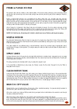
A single stainless steel ¾” Sprayline is a standard fit to all Horizon models. Each complete boom is normally
fitted with seven Sprayline sections all controllable from the cab and each section is fitted with a ‘Duo-React’
nozzle body at ½m spacing.
The spray nozzles will normally be ISO colour coded with outputs to suit.
A 'Top Hat' filter is fitted above every spray tip. Please ensure the flow rate through the 'top hat' filter is
adequate for the tip size.
SPRAY LINES
The system uses mini air valves on the nozzle bodies. The mini air valves will open under air pressure thus
allowing the nozzle to spray, and close under spring pressure thus preventing any further passage of liquid to
the nozzle.
During a 'Spray Off' situation, as in headland turns, filling, field entry etc., residual pumping pressure
(approximately ½ Bar) is used to circulate liquid through the spray lines and back to tank via the purge line. No
liquid is lost through the nozzles because, during 'spray off', the mini valves on the nozzle bodies are closed.
Chemical is being continually agitated and cycled i.e. tank, pump, spray line, tank. All air will be purged from
the spray lines and there will be no chemical 'hot spots'.
When 'Spray On' is selected, the spray pressure will instantly increase. The mini valves will open so that
spraying starts and the purge valve closes so that no liquid returns to the tank via the spray line. 'Spray Off'
reverses the process and instantly washes any accumulated material back to the tank.
NOTE: On 3 fold booms, Pump Speed 2 is better suited to produce effective priming and purging.
PRIME & PURGE SYSTEM
4-3
The standard Nozzle Body fitted to Horizon sprayers is the Hypro Duo-React Twin Valve. This body allows
fitment of up to four nozzles in the forward nozzle position (selectable by rotating the 4 way turret) and a single
in the rearward position.
This body allows for two different sizes of liquid fertiliser nozzles for a wider range of application rates,
operating each singly or both together. The single rearward outlet provides a suitable place for dribble bars or
fertiliser caps.
NOZZLE BODIES
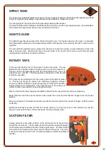
A Clean Water Tank is fitted at the rear of the spray pack below the Main Spray Tank. It should be filled with
clean water from a hose pipe via a Q/R coupling at the rear left-hand side of the machine. A simple 2-way tap
controls water into the tank. Despite a large breather, this tank could be damaged if filling is carried out using a
high capacity pump. There is sufficient water in this tank to enable the largest SAM Spray Tank to be washed
with 10 litres of water for every square meter of tank surface area. A sight gauge is fitted to this tank.
CLEAN WATER TANK
Situated at the rear of the Main Spray Tank on top of the manifold assembly. It is pneumatically operated in
two directions and controls the flow of water to the tank.
When the valve is open (Spray Off) the water being pumped to the manifold takes the easiest route through
the valve and back to the tank.
When the valve is closed (Spray On), the water is pressurised and so travels to the booms
This valve is fitted with a dual O-ring sealing system. If one of these O-rings should fail, liquid will be seen to
leak out of the valve body from the drain hole. A seal kit is available. It is advisable that this valve be serviced
prior to each spraying season simply by stripping it and lubricating the shaft and seals with petroleum jelly.
MAIN ON / OFF VALVE
Содержание Horizon
Страница 5: ...4 SECTION 1 SAFETY ...
Страница 14: ...13 ...
Страница 15: ...14 SECTION 2 MACHINE CONTROLS 2 1 4000 4000E 5500 6000 MACHINES 2 2 3000 3000E 3500 MACHINE ...
Страница 32: ...31 SECTION 3 MECHANICAL COMPONENTS ...
Страница 40: ...39 3 8 TYRES LOAD INDEX TABLE ...
Страница 45: ...44 ...
Страница 46: ...45 SECTION 4 SPRAYING COMPONENTS ...
Страница 53: ...52 SECTION 5 SPRAYING ...
Страница 58: ...57 ...
Страница 59: ...58 SECTION 6 6 1 MAINTENANCE 6 2 Fuses for 3000 3000E 3500 Machine ...
Страница 72: ...71 46 6 2 1 FUSES 3000 MACHINE ...