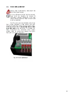
Salus PCSol 150 Скачать руководство пользователя страница 4


1.


SAFE INSTALLATION AND USE 

The  controller is  designed  only  for  household 

and similar use. 

Before  installation,  service  or  maintenance 

and  prior  to  making  any  connections,  always 
disconnect power supply and make sure that the 
terminals and electric wires are not energized. 


When  the  controller  is  switched  off  using 
keyboard, the controller terminals are  still 
under dangerous voltage. 


Controller  may  be  used  only  for  its 
intended purpose. 


It  is  required  to  use  auxiliary  protection 
automatics to protect hot water system (in 
case of controller or software malfunction). 


Programmable  settings  must  be  selected 
suitably  to  your  system  type,  taking  into 
account  all  of  its  operating  conditions. 
Wrongful  settings  may  cause  the  collector 
or  reservoir  malfunction  (e.g.  collector 
overheating, etc.). 


Programmed  settings  may  be  modified 
only by a person who read and understood 
this manual. 


Use  only  in  heating  systems  that  are  set 
up in accordance with valid regulations. 


Electric  system  to  which  the  controller  is 
connected  must  be  protected  with  a  cut-
out device suitable for expected loads. 


Never use the controller when its casing is 
damaged. 


In  any  case  do  not  alter  the  controller 
components. 


The  controller  has  micro-disconnection  for 
connected 

devices 

(operation 

2.B 

according  to  PN-EN  60730-1).  It  means 
that  at  230V  voltage  supply  the  pump 
outlets  have  dangerous  voltage,  even  if 
the pumps are not controlled. 


Do  not  allow  children  access  to  the 
controller. 


Before  you  open  casing,  first  disconnect 
power supply from the unit. 


The  controller  must  be  installed  in 
accordance  to  the  requirements  of  EN 
60335-1  standard,  by  qualified  and 
authorized technician. 


Do  not  install  the  unit  when  connected  to 
voltage. 


Do  not  operate  the  unit  when  it  is 
malfunctioning  or  was  repaired  by 
unauthorized persons. 
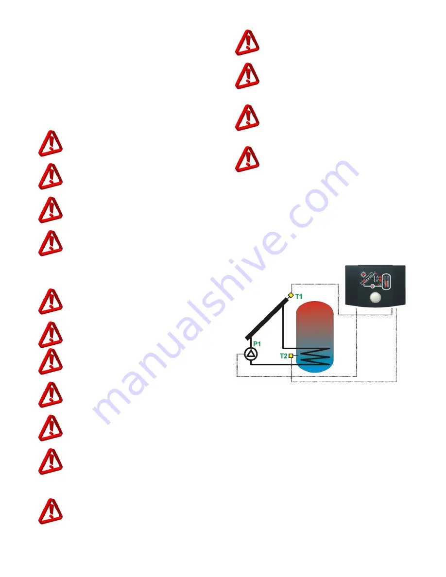
 

2.


GENERAL 

PCSol  150  is  an  advanced  electronic 

temperature  controller  designed  for  heat 
distribution  from  solar  collectors  to  hot  utility 
water  reservoir. The controller is used to control 
solar  circuit  systems  accordingly  to  indications 
from  temperature  sensors  to  recover  highest 
possible energy from the collector. 


Fig. 2.1 Functional diagram 

Содержание PCSol 150

Страница 1: ...Controller PCSol 150 REVISION 1 1 SOFTWARE 1 xx 26 05 2015 FOR SOLAR COLLECTORS INSTALLATION AND OPERATION MANUAL...

Страница 2: ......

Страница 3: ...diagram of connections 16 12 1 1 Use of connectors 17 12 1 2 Power supply connection 17 12 1 3 Temperature sensor connection 17 13 HOW TO CLOSE CASING 18 14 FUSE REPLACEMENT 19 15 TROUBLESHOOTING 20 L...

Страница 4: ...c system to which the controller is connected must be protected with a cut out device suitable for expected loads Never use the controller when its casing is damaged In any case do not alter the contr...

Страница 5: ...and electronic products disposal system It is recommended to process in accordance with local regulations and not to dispose used products to household garbage containers Proper disposal of outdated...

Страница 6: ...6...

Страница 7: ...OPERATING MANUAL PCSol 150...

Страница 8: ...long with the temperature rise Measured temperature is shown with the step of 10 C for T1 sensor collector s temperature and 5 C for T2 sensor DHW reservoir temperature Subsequent segments of the indi...

Страница 9: ...llector temperature TCOLmin move the cursor to the indicator with sun symbol Press the knob sun symbol will start fast blinking to enter value editing mode You may change the value by turning the knob...

Страница 10: ...ted by illumination of the sun symbol indicator When the collector temperature drops two degrees below minimal temperature preset the sun symbol will go off and the controller will disable the collect...

Страница 11: ...n interruption Alarm on incorrect operation or damage to T2 sensor Signals interruption in T2 sensor circuit Check if the sensor is not e g off the unit or the connecting wire is cut Collector pump op...

Страница 12: ...roller off the pump operation will be stopped 9 1 Test of unit When switched on the unit undergoes some testing At the time the display shows alternately the testing screen and the software version Te...

Страница 13: ...INSTALLATION MANUAL PCSol 150...

Страница 14: ...the set Controller PCSol 150 Temperature sensor T1 CT6w Temperature sensor T2 CT6 Installation and operating manual 1 pc 1 pc 1 pc 1 pc 11 INSTALLATION The controller is designed for operation in the...

Страница 15: ...ust and water access is prevented Permissible operating temperature is not exceeded 40 C for controller Air exchange inside casing is allowed Access to dangerous parts is disabled Electrical installat...

Страница 16: ...in sections 12 1 2 12 1 3 Presented hydraulic diagram will not replace central heating technical design and may be used only for informative purposes Collector and hot water reservoir must be install...

Страница 17: ...act surfaces with temperatures that exceed the cables operating temperature limits The controller has no PE protective connector because the controller itself does not require grounding PE terminals o...

Страница 18: ...r must be located in thermometric tube between the supply and return connectors of the collector exchanger pipe coil The sensors resistance per temperature table CT6w CT6 Temp C Min Nom Max 0 999 7 10...

Страница 19: ...t means that the fuse is burnt and must be replaced For the unit use sub miniature slow blow fuse 1 25A compliant to IEC 60127 and with maximum switching current not lower than 100A Example of such fu...

Страница 20: ...Collector pump capacity is too low pump is not able to transfer heat to reservoir exchanger 3 Temperature preset for reservoir has been reached and controller has disabled the pump Collector pump is...

Страница 21: ...Presented drawing is in 1 1 scale and it may be helpful during installation You may cut off this page and use to mark installation place Fig 15 1 Casing drawing for installation aid...

Страница 22: ......

Страница 23: ......

Страница 24: ...SALUS Controls Made in Poland...

Отзывы: