Tel: 886. 909 602 109 Email: [email protected]
www.salukitec.com
52
Table 6. Filter Configuration
Time Constant
10μs
3ms
1s
300s
30μs
10ms
3s
1000s
100μs
30ms
10s
3000s
300μs
100ms
30s
1ms
300ms
100s
Filter Slope
6dB/oct
12dB/oct
18dB/oct
24dB/oct
SYNC Filter
Disable
Enable
Note that:
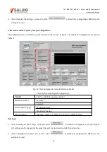
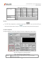
The SYNC Filter configuration is controlled by a single button
. If you need to turn off the sync
filter, click the button and then it changes to
which means the sync filter has been turned off.
8. Output Configuration
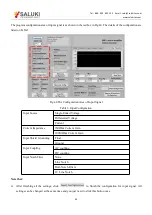
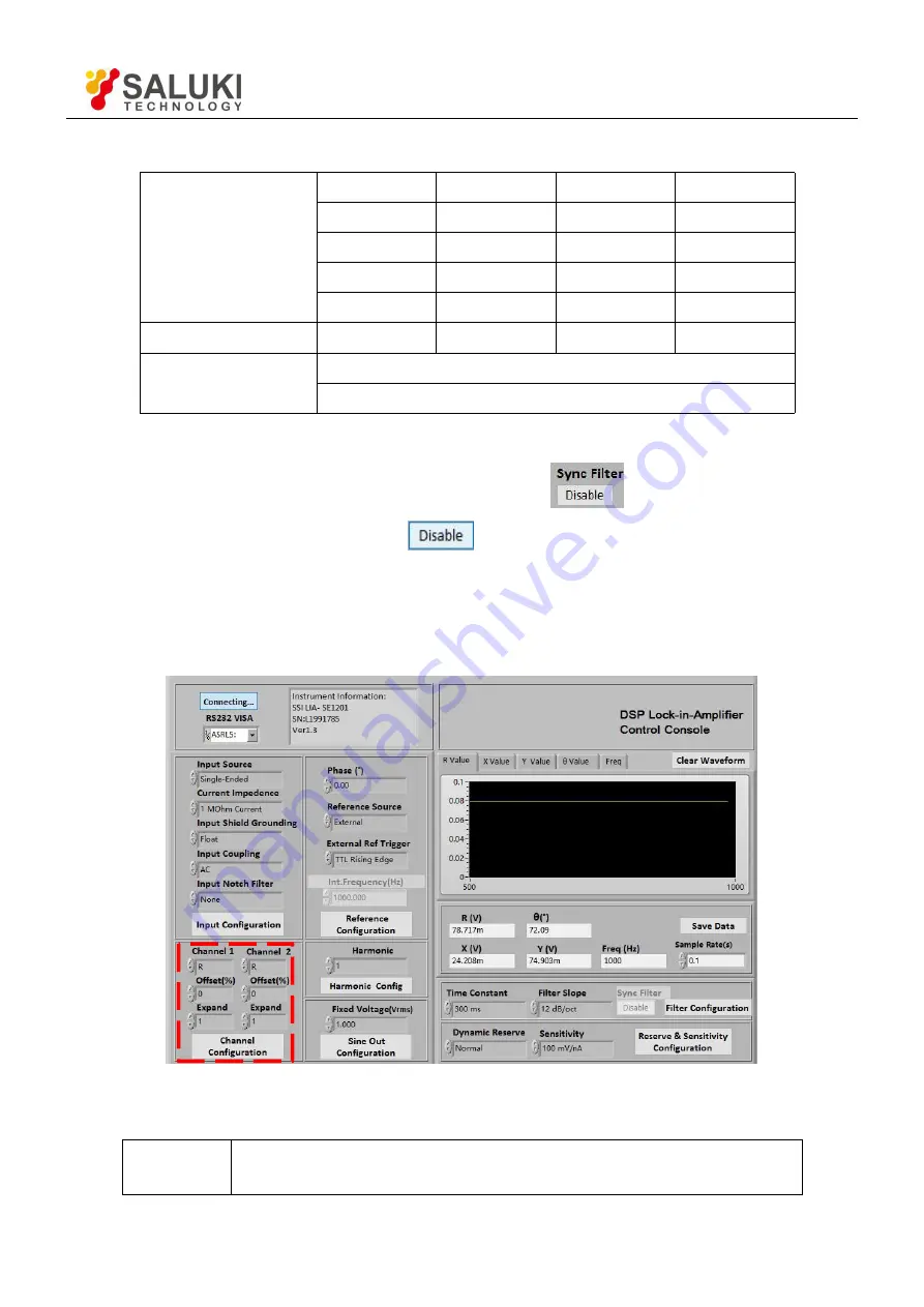
The output configuration is in the red box in the Fig.45. The details of configuration are shown in Table 7.
Fig.45 The Configuration Area of Output Channel
Table 7. Output Channels Configuration Options
Channel 1
Choose CH1 to output the required values. The value types contain the
X/Y/R/θ value of signal.

