background image

Service

EN

GFA-OOT

10

© Saltus Industrial Technique AB - 9839 1814 01

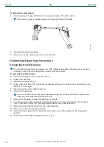
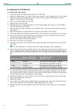
To lubricate the GFA module:

1.

Use a grease gun to apply lubrication to every grease nipple of the GFA module.

The number of grease nipples varies with the design of the GFA module.

2.

Operate the system a few times.

3.

Remove any excess grease with a clean, smooth cloth.

Dismantling/Assembling Instructions

Dismantling the GFA Module

The instruction below shows an example of a GFA module. The module comprises a housing which
contains a number of gears depending on model of the GFA system.

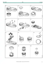
To dismantle the GFA module:

1.

Secure the housing in a vice and loosen the nut.

2.

Loosen the cover cap.

3.

Remove the bearing housing.

4.

Loosen the hex screws. The module can be fastened with two or four hex screws, depending on the
model (2, 3, or 4-stage).

5.

Open the housing using a flat screwdriver.

6.

Remove the output gear.

Note the direction of the output gear (hexagonal shape up or down). It should be placed in the
same way when assembling the GFA module.

7.

Remove the idle gears, needle roller bearings, and shafts.

8.

Turn the input gear all the way back to the locked position. Then turn it forward 1/4 of a revolution.
Push in the pawl by using a 0.1 mm feeler gauge. Remove the collar back latch.

9.

Remove the pawl and the spring from the collar back latch.

10. Remove the nut from the bearing housing.

11. Remove the input gear from the bearing housing. Remove the ball bearing from the input gear if

needed.

12. Remove the needle roller bearing from the input gear.

Содержание GFA-OOT

Страница 1: ...from Serial No Product Instructions Open end and Offset Geared Front Attachments WARNING Read all safety warnings and instructions Failure to follow the safety warnings and instructions may result in...

Страница 2: ...2 Saltus Industrial Technique AB 9839 1814 01 Table of Contents EN Product Instructions 3...

Страница 3: ...ch if not avoided will result in death or se rious injury WARNING WARNING indicates a hazardous situation which if not avoided could result in death or serious injury CAUTION CAUTION used with the saf...

Страница 4: ...GFA module The GFA module comprises a housing which contains a number of gears that is the gear stage The gear stage depends on the length of the GFA module The output gear or output socket can be of...

Страница 5: ...y Instructions The assembly procedure varies depending on the configuration Make sure that the square drive of the drive unit 1 matches the input gear profile square hole of the GFA module 2 Functiona...

Страница 6: ...ing it in one direction should lock the wheel In the other di rection the gear wheel should be turned easily The direction for locking clockwise or counterclock wise depends on the configuration of th...

Страница 7: ...priate lighting for the work task Select the appropriate tool for the work task In noisy environments use ear protection equipment Use high quality inserted tools and consumables to minimize exposure...

Страница 8: ...being used Wrong Parameter File might cause too high torque with bodily injury as a result Compare the maximum torque which is shown in the controller with the maximum torque stated in the stated tech...

Страница 9: ...ly Clean the GFA system Inspect the system for any damage Check all fastenings of the system Run functional tests and listen for any abnormal noise At least after every 30 000 tightenings Lubricate th...

Страница 10: ...p 3 Remove the bearing housing 4 Loosen the hex screws The module can be fastened with two or four hex screws depending on the model 2 3 or 4 stage 5 Open the housing using a flat screwdriver 6 Remove...

Страница 11: ...GFA OOT EN Service Saltus Industrial Technique AB 9839 1814 01 11...

Страница 12: ...e collar back latch can include a torque arm flange depending on the configuration 14 Push in the pawl and put the collar back latch over the bearing housing The pawl should go into one of the two gro...

Страница 13: ...GFA OOT EN Service Saltus Industrial Technique AB 9839 1814 01 13...

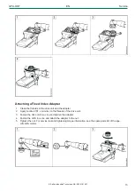
Страница 14: ...tool information see the spare parts list of the specific GFA model 3 Remove the adapter together with the drive unit from the GFA unit 4 Fasten the drive unit in a vice Loosen the adapter clockwise t...

Страница 15: ...ve unit and the adapter 2 Apply Loctite 2701 or similar to the threads of the drive unit 3 Fasten the drive unit in a vice and tighten the adapter 4 Fasten the GFA in a vice and attach the adapter to...

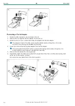
Страница 16: ...strong force It is recom mended to use a heat gun to facilitate the loosening 4 Loosen and remove the bearing shell adapter from the fork adapter The bearing shell is fixed with Loctite Loosening the...

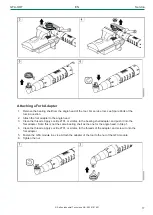
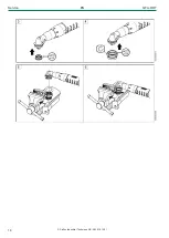
Страница 17: ...the angle head 3 Clean the threads Apply Loctite 2701 or similar to the bearing shell adapter and push it into the fork adapter Note this is not the same bearing shell as the one for the angle head i...

Страница 18: ...Service EN GFA OOT 18 Saltus Industrial Technique AB 9839 1814 01...

Страница 19: ...ecycling Environmental Regulations When a product has served its purpose it has to be recycled properly Dismantle the product and recycle the components in accordance with local legislation Batteries...

Страница 20: ...or copying of the contents or part thereof is prohibited This applies in particular to trademarks model denominations part numbers and drawings Use only authorized parts Any damage or malfunction caus...

Отзывы: