background image

7

 1 

 2 

 3 

 4 

 5 

 6 

 7 


 1 

 2 

 3 

 4 

 5 

 6 

 7 

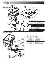
TGS03 Tailgate Auger

TGS03 Hopper Assembly

Bill of Materials

Bill of Materials

ITEM  PART NO. 

QTY.  DESCRIPTION

3019372 

1  HOPPER ASSEMBLY

3026555

1 HOPPER ASSEMBLY, RED

3026557

1 HOPPER ASSEMBLY, YELLOW

2  3019400 

1  FRAME TGS03

3019410 

1  LID TGS03

3026564

1 LID TGS03, RED

3026565

1 LID TGS03, YELLOW

4  3019561 

1  SPINNER, 12 IN TGS

5  3015707 

1  SHIELD TGS07

6  3018923 

1  DISC PROTECTOR

7  3019408 

1  HARDWARE BAG TGS03

ITEM 

PART NO. 

QTY.  DESCRIPTION

3015383 

1

TROUGH ASSEMBLY TGS07

3019471 

1

HOPPER POLY

3026554

1

HOPPER POLY, RED

3026556

1

HOPPER POLY, YELLOW

FWF031075006SS  6

WASHER, 5/16 SAE SST

3006721 

6

SCREW, HEX HD, 5/16-18 X 3/4 GR5 SS

3015694 

1

MOTOR COVER TGS07

3015925

4

SCREW #14X1.25 SST

3017984

1

CAP ROUND 1.312 ID VINYL BLACK

Содержание TGS03

Страница 1: ...scovered and returned part s are found to be defective by Buyers Products Company Authorization from Buyers Products Company must be obtained before returning any part The following information must accompany defective parts returned to Buyers Products Company RMA spreader model serial number date installed and distributor from whom purchased Buyers Products Company shall not be liable for damage ...

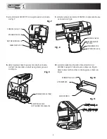
Страница 2: ...2 1 Slide frame 3019400 into hitch receiver Fig 1 2 Slide hopper assembly 3019372 between frame uprights with front portion rested on the truck s bumper Fig 2 Fig 1 Fig 2 ...

Страница 3: ...on all stainless steel fasteners to avoid galling 4 Slide hopper and frame towards tailgate leaving about 3 8 to space Align closest holes in hitch receiver with holes in frame Secure frame in hitch receiver using 5 8 hitch pin and cotter pin Fig 4 5 Assembly 13 x 6 0 screws as shown in Fig 5 Make sure that nuts located between hopper flange and frame positioned exactly as shown These nuts must no...

Страница 4: ... as shown in Fig 9 Secure disk on shaft using clevis pin and cotter pin CATCH LATCH WC215 SCREW 10 24 X 75 SPINNER DISK 3019561 CLEVIS PIN1420014 COTTER PIN FPC007800075 NUT NYLOCK 3 8 16 WASHER FLAT 3 8 SCREW 3 8 16 X 1 0 SHIELD 3015707 7 Attach shield 3015707 to trough bracket as shown in Fig 7 SCREW 3 8 16 X 2 0 DISC PROTECTOR 3018923 WASHER FLAT 3 8 NUT NYLOCK 3 8 16 Fig 8 8 Attach spinner pro...

Страница 5: ...T CONNECT TO BATTERY AT THIS TIME Lay out path for wire harness to the rear of the vehicle It is recommended to stay clear of the exhaust system Excess heat can damage the wire harnesses Use quick ties to secure harness to underbody Connect the wire harness to the motor and vibrator Connect the power and ground cables directly to the battery Insure all functions of the controller are working prope...

Страница 6: ...ru hopper using bind holes as guides Place plate inside hopper align holes in plate with holes in hopper Place vibrator on outer hopper wall and secure it to hopper using 4 carriage bolts 3 8 16 x 3 25 and 4 nylock nuts 3 8 16 Connect vibrator cable to mat ing connector on wire harness 3008620 Check fasteners every 5 7 hours of operation Retighten if necessary Controller Warnings Check controller ...

Страница 7: ...1 LID TGS03 RED 3026565 1 LID TGS03 YELLOW 4 3019561 1 SPINNER 12 IN TGS 5 3015707 1 SHIELD TGS07 6 3018923 1 DISC PROTECTOR 7 3019408 1 HARDWARE BAG TGS03 ITEM PART NO QTY DESCRIPTION 1 3015383 1 TROUGH ASSEMBLY TGS07 2 3019471 1 HOPPER POLY 3026554 1 HOPPER POLY RED 3026556 1 HOPPER POLY YELLOW 3 FWF031075006SS 6 WASHER 5 16 SAE SST 4 3006721 6 SCREW HEX HD 5 16 18 X 3 4 GR5 SS 5 3015694 1 MOTOR...

Страница 8: ...3011864 1 CONTROLLER TGS W VIBRATOR SWITCH 2 3008615 1 WIRE HARNESS POWER TGS 3 3008620 1 WIRE HARNESS MAIN W VIBRATOR TGS 4 3017039 2 SCREW HEX HEAD CAP 1 2 13 X 6 00 SST FULL THREAD 5 3001523 4 NUT HX FLNG 1 2 13 SST 6 3000269 10 WASHER FLAT 1 2 USS SST 7 3001250 4 SCREW HHC 1 2 13 X 3 SST 8 FNE050013053SS 6 NUT NYLOCK 1 2 13 SS 9 1420014 1 PIN CLEVIS 1 4 X 2 5 10 FPC007800075 1 COTTER PIN 5 64 ...

Отзывы: