
46
SALICRU
4.
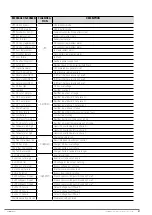
The inverter should restart, and you will recover the
normal operating mode of the UPS.
"UPS Status" should
show "UPS Running", and on the main screen, the power
flow will correspond to the one shown in
.
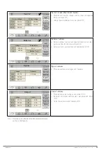
6.2. PROCEDURE FOR STOPPING THE UPS
This section describes the correct procedure for complete shut-
down of the UPS, leaving the loads without power, and the UPS
without any voltage at any of its input and output terminals
(and batteries, if any).
This procedure may be necessary in interventions to change the
installation, remove the UPS, replace it, etc.
With the UPS operating in normal mode (synoptic shown in
, and in the "Status and Control" submenu you can see
that the "UPS Status" shows "UPS Running"), in order to shut it
down completely, proceed as follows:
1.
Stop the loads (or set their switches on the distribu-
tion board to "Off", if any) progressively.
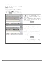
2.
Press the "Status and Control" icon
You are
3.
Press the "Start/Stop UPS" icon
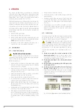
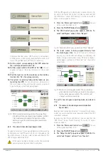
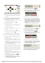
4.
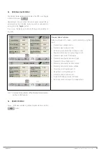
The "UPS Control" pop-up box appears, with the "Start"
and "Stop" options. Press "Stop".
Fig. 58.
"UPS Control" pop-up window. Press "Stop".
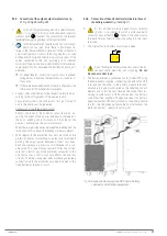
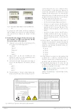
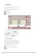
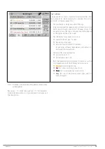
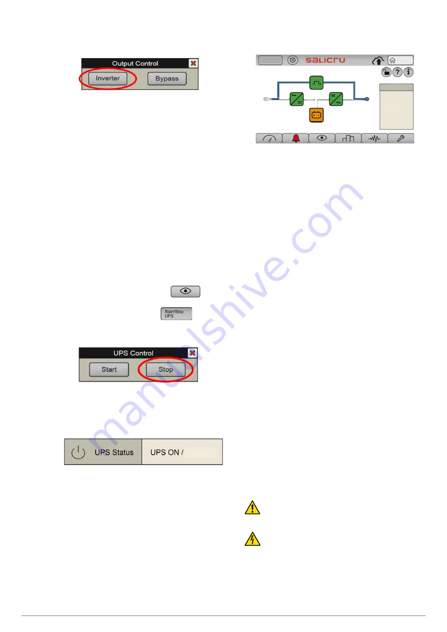
5.
You can check the status on "Stand-By" of the UPS
.
The "UPS Status" field (Status and Control" submenu, see
) shows:
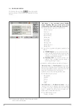
Stand-By
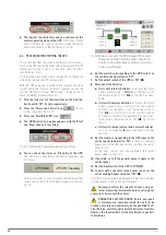
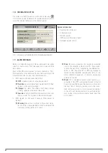
On the main screen, you can also check that the power flow
corresponds to that of the UPS when stopped, as shown in
.
Log In
Home
Load
2020-09-15
07:28:06
L1
231. 8
L2
233. 5
L3
232. 8
L1
229. 6
L2
229. 4
L3
230. 1
L1
0. 2%
L2
1. 0%
L3
0. 2%
Tot
0. 2%
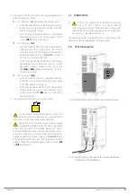
Fig. 59.
Main screen with the UPS stopped. The power
flow goes directly from the bypass input to the
output, via the static bypass switch, and all con-
verters are stopped.
6.
Set the switch corresponding to the UPS output on
the control panel (external) to "Off".
7.
Set the output switch of the UPS to "Off" (
Q2
).
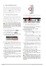
8.
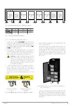
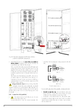
Disconnect the batteries:
a.
Units with internal batteries:
disconnect the 3-pole
battery connector (
Detail A
the battery switch to "Off" (
Q6
, on the front), as appli-
cable.
b.
Units with external batteries:
disconnect the 3-pole
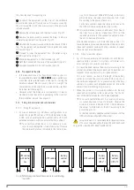
Fig. 3 and Fig. 4 for 30 kVA and 40
kVA units,
on the back), or set the battery switch to
"Off" (
Q3,
Fig. 7 and Fig. 8 for 50 kVA, 60 kVA and 80
kVA units,
on the front), as applicable. Also, set the ex-
ternal battery cabinet switch to "Off"
(Q8
,
c.
Units with shared internal and external batteries:
carry out points
a.
and
b.
described above one after
the other.
9.
Set the switch corresponding to the UPS input on the
control panel (external) to "Off".
If there is a separate
bypass line for the UPS, also set this switch on the control
panel to "Off".
At this point, the unit will stop completely (the control
panel screen switches off).
10.
If possible, cut off the general power supply to the
control panel.
11.
Set the input switch of the UPS to "Off"
(Q1)
.
12.
In units with a separate static bypass input, set the
corresponding bypass switch to "Off" (
Q4
).
The UPS is now completely de-energised, there is no voltage at
its input, bypass, battery and output terminals.
However, perform the relevant checks using ex-
ternal measuring instruments before carrying out
any work to disconnect the cables.
DANGER OF ELECTRIC SHOCK: before any repair
or maintenance operation inside the unit, to be
carried out solely and exclusively by the qualified Tech-
nical Service, wait for approximately 5 minutes from this
moment, the required time for the electrolytic capacitors
to discharge.
Содержание SLC CUBE 4
Страница 1: ...30 80 kVA USER MANUAL UNINTERRUPTIBLE POWER SUPPLY...
Страница 74: ...74 SALICRU...
Страница 75: ...75 SLC CUBE4 UNINTERRUPTIBLE POWER SUPPLY SYSTEM USER MANUAL...
Страница 76: ...76 SALICRU...
Страница 77: ...77 SLC CUBE4 UNINTERRUPTIBLE POWER SUPPLY SYSTEM USER MANUAL...