


9
5. INSTALLATION
•
Read and follow all of the Safety Information set out
or linked in chapter 2 of this document. Failure to
adhere to any of the indications set out may cause a serious
or very serious accident for those who are in direct contact
with the unit or who are in the vicinity, as well as faults in
the bypass panel, the unit or units, and/or in the loads con-
nected to the system.
•
Check that the information on the name plate is the right
information for the installation.
•
A bad connection or operation can cause faults in the panel,
the unit or units, and/or the loads connected to the system.
Read the instructions in this manual carefully and follow
the steps in the corresponding order.
•
Only proceed with the connection if all of the switches
on the unit or units that make up the system are set to
standby and there is no mains supply present (disconnect
switch(es) of the power line(s) for the panel set to “OFF”).
•
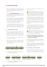
All of the bypass panel connections described in this document
will be implemented according to the labels on the unit, which
in turn is based on the respective block diagrams. In structural
terms, there are six different types of panel, regardless of their
possible configurations (L, M, N, etc.):
Generic manual bypass panel for a standard UPS (Fig. 3).
Generic manual bypass panel for a UPS with a separate
bypass line (Fig. 4).
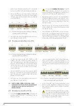
Manual bypass panel for “n” standard parallel or re-
dundant UPSs (Fig. 5). For UPS series CUBE3+, CUBE4 and
TWIN PRO2.
Manual bypass panel for “n” standard parallel or redundant
UPSs (Fig. 6), for UPS series ADAPT, ADAPT-X, ADAPT2,
TWIN PRO2, X-PERT and X-TRA.
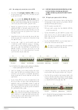
Manual bypass panel for “n” parallel or redundant UPSs
with a separate bypass line (Fig. 7), for UPS series CUBE3+
and CUBE4.
Manual bypass panel for “n” parallel or redundant UPSs
with a separate bypass line (Fig. 8), for UPS series ADAPT,
ADAPT-X, ADAPT2, X-PERT and X-TRA.
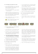
Beyond the structures indicated, there are slight nuances in
terms of control connections between panels for each UPS
range, which are clarified later in this chapter.
•
The figures in this document are by way of example, and are
intended to show the linear and orderly layout of the operating
mechanisms, without considering the physical format that
may correspond to the unit’s power. Another factor to consider
is the
optional
version shown in all figures,
“
P
”,
which corre-
sponds to operating mechanisms via circuit breakers.
•
Depending on the panel model, the enclosure may vary (plastic
or metal box, or metal cabinet), so the adjacency between them
could be affected, although the order would be maintained.
•
Depending on the power of the bypass panel and the version
requested, the operating mechanisms may vary in number
(parallel systems), in number of poles (according to the con-
figuration), format, size and type (disconnect switch or circuit
breaker), but they will always be identified via the labels.
Pay attention to the steps indicated for any change in
the operating mode, following the identification la-
bels on the operating mechanisms.
•
The manual bypass panel version with a separate static bypass
line (-B), has additional connection and operating elements that
are only available in this version. Disregard all references to
them for the standard or basic version.
5.1. TO BE CONSIDERED IN THE INSTALLATION
•
These instructions are generic for any manual bypass panel
from this series. Disregard unavailable terminal connections.
•
All connections to the panel are made via terminals. However,
on some models, and due to their high power or current, cables
are connected directly to the disconnect switch or switch plates.
•
In terms of the earth and earth bonding cable connection, the
panels usually have two points on opposite ends, generally
threaded studs.
•
In the documentation provided on CD-ROM together
with each UPS, the information relating to the “Recom-
mended Installation” is included for each of the input and
output configurations. It shows the wiring diagrams, as well as
the protection size and the minimum cross-sections of the ca-
bles connected to the unit, according to its nominal working
voltage. All values are calculated for a
total maximum cable
length of 30 m
between the distribution board, unit and loads.
For longer lengths, correct the cross-sections to prevent
voltage drops, observing the regulations or standards
of the country.
In the same documentation and for each configuration, the
information for “N” parallel units is available, as well as the
characteristics of the “Backfeed protection”.
All indications relating to the “Backfeed protection”
referred to in the UPS user manual must be followed,
considering the availability or not of the separate static
bypass line and the corresponding actions to be taken in
each case.
•
In parallel systems, the length and cross-section of
the cables that run from the protection board to
each UPS and from these to the board will be the same for
all of them without exception.
USER'S MANUAL
Содержание SLC ADAPT
Страница 2: ...2 SALICRU...
Страница 21: ...21 USER S MANUAL...