37
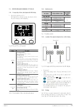
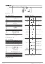
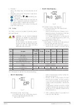
Parameter 2 setting. HS.H
–
Enabling or disabling the Hot standby function.
Parameter 3 setting:
–
YES: The Hot standby function is enabled after
the mains are restored even without the batteries
being connected to the UPS.
–
NO: The Hot standby function is disabled. The UPS
operates in normal mode. It will not restart if the
batteries are not connected to the UPS.
•
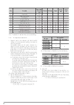
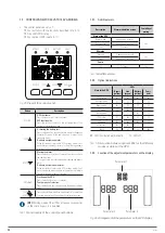
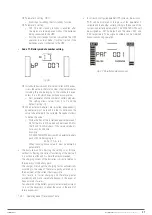
Code 17 -Battery module number setting.
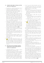
Fig. 36.
In standard devices with internal batteries or B1 devices,
it sets the value to the total number of battery modules
including the one belonging to the standard device,
unless it is a B1 which does not have accumulators.
–
Sets parameter 3 to the number of battery modules.
The setting allows values from 0 to 7 and the
default setting is 0.
When external batteries are installed independently,
equivalence must be found in order to determine the
value to be entered in this variable. Proceed as follows
to define the value:
–
Divide the Ahs of the installed batteries between 7
Ah for the 4 to 6 kVA models and between 9 Ah for
the 8 and 10 kVA models. If the value obtained is
not exact, round down.
Example:
SLC 5000 TWIN RT2 device with an external battery
pack of 45 Ah belonging to it.
45 Ah / 7 Ah = 6.4
When rounding down, value ‘6’ must be entered in
parameter 3.
•
The basic reason for adjusting the setting is as follows,
without it affecting the correct functioning of the device if
it is not done, although it is more than recommended:
The charging current of the batteries is directly related to
the capacity of the battery pack.
The charger will adapt the charging factor automatically
according to the value of the total capacity entered, up to
the maximum of the current that is possible.
This results in faster charging and therefore greater
availability and more immediate backup in the event of
frequent mains failures.
Any alteration of the battery pack will entail a readjustment,
so it will be necessary to adapt the value in the event of
future expansions.
7.3.4.1. Operating mode / Description of state.
•
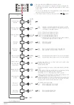
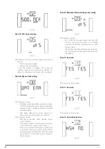
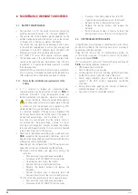
In correctly configured parallel UPS systems, the acronym
‘PAR
’
will be displayed in the place of the parameter 2
variable and the number corresponding to the device of the
system in parallel in parameter 3. The ‘MASTER
’
UPSs will
be assigned as ‘001
’
by default and the slaves ‘002
’
and
‘003
’
respectively. The assigned numbers can be modified
dynamically during operation.
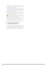
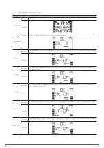
Fig. 37.
Parallel system screen.
SLC TWIN PRO2
UNINTERRUPTIBLE POWER SUPPLY SYSTEMS (UPS)
USER MANUAL


