


24
5. Single line diagram,
description and structural
diagram of the system.
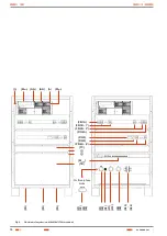
5.1. Single line diagram.
Input filter
DC / DC
converter
Output
filter
PFC 1
Rectifier
BATTERIES
PFC 1
Control
Input
power
supply
DC / DC
Control
Output
power
supply
Micro.
Control
AC
IN
PU
T AC
DC
O
UT
PUT
CONTROL
MODULE
COM
MODULE
RECTIFIER
MODULE
END OF BACK
UP TIME
CONTACTOR
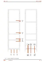
Fig. 14.
Single line diagram.
5.2. Description.
The operating principle of the Rectifier Module, entails trans-
forming the alternating input voltage, fitted out with a line filter
previously, into a direct voltage by converting, rectifying and con-
trolling.
By means of a ultrafast transistors with high quality performances
and starting from a direct voltage of 385 V DC , an alternating
voltage of 90kHz is generated by means of a DC / DC converter.
Then, it is rectified by ultrafast diodes and fitted out with an ef-
ficient filtering system.
A transformer of special power, which galvanically isolates the
input from output, decreases the high frequency alternating
voltage to the required value to generate the final wanted direct
voltage.
The output voltage and current are managed by the pulse width
modulation of the transistors, fitted in the primary of the trans-
former. The resulting Rectifier Module/s are available in powers
of 1000, 2000 and 2700 W and in voltages 24, 48, 110, 125 or
220 V DC.
The rectifier input is single phase, which allows manufacturing
systems in both configurations, single or three phase, depending
on the needs of the end-user and the power of the equipment.
The parallelable feature of the rectifiers and the capacity of
storing energy in the batteries for long back up times, makes the
DC Power-S appropriate for different kind of high technology ap-
plications.
All rectifiers are autoadressing, Plug-in and Hot swap type
through the front of the cabinet, and it is not needed any special
tool, just a screwdriver. This feature allows removing the faulty
modules and/or insert new modules into the system, without the
need of shutdown the system, on condition that the drain power
is not higher than the modules in service.
5.2.1. Control Module.
The Control Module supervises and manages the complete
DC Power-S system by means of a microprocessor, which is in
charge of controlling the settings and displayed measurements
in the own LCD panel too: input and output measurements,
battery charging currents, critical and non-critical load control,
communication channel with the environment, ... The maximum
quantity of rectifiers in parallel that it can manage is 30, being
able to get systems up to 81 kW, with «N+n» redundant configu-
ration options.
5.2.2. Communication Module (COM).
Any system includes the basic version of the Communication
Module (COM) which has three programmable dry contacts,
RS232/485 channel mutually exclusive between them, battery
temperature probe for its measurement and compensating the
floating voltage of itself and one slot for the Ethernet/SNMP
adaptor. Its extended version includes six additional dry contacts
and the input of the electrolyte level probe for flooded batteries.
5.2.2.1. Dry contacts.
By means of the communication interface with dry contacts and
digital inputs, it can interact with the environment in the event
of alarms of the system or notifications received by the environ-
ment.
USER MANUAL
Содержание DC POWER-S DC-10-S
Страница 2: ......
Страница 18: ...18 Case with casters dimensions Cabinet dimensions 605x605x1315 mm 605x805x1315 mm USER MANUAL...
Страница 42: ...42 USER MANUAL...
Страница 43: ...43 SALICRU...


