Salicru DC POWER-S DC-10-S Скачать руководство пользователя страница 1

UNINTERRUPTIBLE POWER SUPPLY (UPS) + LIGHTING FLOW DIMMER STABILIZERS (ILUEST) + SWITCH MODE POWER STATIC INV PHOTOVOLTAIC INV VOLTAGE STABILIZERS AND POWER LINE CONDITIONERS

USER'S MANUAL

DC POWER SYSTEMS

DC POWER-S Series

Содержание DC POWER-S DC-10-S

Страница 1: ...OWER SUPPLY UPS LIGHTING FLOW DIMMER STABILIZERS ILUEST SWITCH MODE POWER SUPPLY STATIC INVERTERS PHOTOVOLTAIC INVERTERS VOLTAGE STABILIZERS AND POWER LINE CONDITIONERS USER S MANUAL DC POWER SYSTEMS...

Страница 2: ......

Страница 3: ...and or X5A 7 5 Connection of the system with the battery set or cabinet Terminals X11 X12 and X47 X48 7 6 Connection to AC mains Terminals X1 X2 X3 and X4 7 7 Connection of the loads 7 7 1 No DC outg...

Страница 4: ...or specifi cally authorised Although no effort has been spared to guarantee that the information in this manual is complete and accurate we are not responsible of any errors or omissions that may exi...

Страница 5: ...e mandatory to endow it with the appro priate protection degree either with an individual metallic enclosure or integrated in a cabinet together with other equip ments that belong to the installation...

Страница 6: ...Reference Standard IEC EN 60950 1 Information technology equipment Safety Part 1 General requirements IEC EN 61204 3 DC low voltage supply devices Part 3 Electromagnetic Compatibility EMC The manufac...

Страница 7: ...nderstanding of the instal lation and or commissioning and shutdown procedures of the system The DC Power S system can be supplied in the following ver sions 19 Subrack with 4 U height and designed to...

Страница 8: ...to not break the earthed pole As terminal block in the DC outgoing distribution with floating output will be used the own terminals of the protections For outputs positive or negative earthed the term...

Страница 9: ...2 t1 RU Mrect Fig 4 Case with casters view AS1 t1 Mrect Mcont AS2 t2 F Q1A F Q1B 1 F Q2B 2 F Q2A F Q3 F Q2 F Q6A 6 TC t4 t3 Mcom TB X40 X46 X6 X9 X11 X12 X1 X4 X5 R N For three phase mains R S T N X1...

Страница 10: ...AS1 F Q1A F Q1B 1 F Q2B 2 F Q2A F Q3 F Q2 F Q6A 6 TC t4 t3 Mcom TB X40 X46 X6 X9 X11 X12 X1 X4 X5 R N For three phase mains R S T N X1 X2 X3 X4 PR PR PR Fig 6 Front view of a system in a 605x805x1315...

Страница 11: ...Mcont AS2 t2 F Q1A F Q1B 1 F Q2B 2 F Q2A F Q3 F Q2 F Q6A 6 TC t4 TC t4 t3 TB Mcom X40 X6 X9 X11 X12 X1 X4 X5 R N For three phase mains R S T N X1 X2 X3 X4 PR PR PR Fig 7 Front view of a system in a 6...

Страница 12: ...nt AS2 AS1 F Q1A F Q1B 1 F Q2B 2 F Q2A F Q3 F Q2 F Q6A 6 TC t4 TC t4 t3 TB Mcom X40 X46 X6 X9 X11 X12 X1 X4 X5 R N For three phase mains R S T N X1 X2 X3 X4 Fig 8 Front view of a system in a 605x805x2...

Страница 13: ...13 SALICRU TC t4 TC t4 TC t4 t3 TB X47 X48 X5A F Q8 X43 X25A PR PR PR Fig 9 Front view of 605x605x1315 mm battery cabinet...

Страница 14: ...14 TC t4 TC t4 TC t4 t3 TB X47 X48 X5A F Q8 X43 X25A PR PR PR Fig 10 Front view of 605x805x1315 mm battery cabinet USER MANUAL...

Страница 15: ...15 SALICRU TC t4 TC t4 TC t4 t3 TB X47 X48 X5A F Q8 X43 X25A PR PR PR Fig 11 Front view of 605x605x2115 mm battery cabinet...

Страница 16: ...16 TC t4 TC t4 TC t4 t3 TB X47 X48 X5A F Q8 X43 X25A PR PR PR Fig 12 Front view of 605x805x2115 mm battery cabinet USER MANUAL...

Страница 17: ...17 SALICRU 4 1 1 Dimensional drawings Rectifier module dimensions 19 subrack dimensions Table top case dimensions...

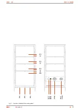
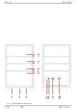
Страница 18: ...18 Case with casters dimensions Cabinet dimensions 605x605x1315 mm 605x805x1315 mm USER MANUAL...

Страница 19: ...19 SALICRU Dimensions for equipment cabinets or batteries regardless illustration 605x605x2115 mm 605x805x2115 mm 805x805x2115 mm Fig 13 Dimensional drawings...

Страница 20: ...ary contact terminals general outgoing distri bution protection F Q2 3 X46A 46 Auxiliary contact terminals single outgoing distribu tion protection F Q6A 6 3 X47 Positive battery terminal in the batte...

Страница 21: ...tifier and or battery cabinet op tional PF1 Fixing points at the front of the subrack PF2 Fixing points of the telescopic guide GS of the sub rack PI Elevator parts feet PR Cable gland for cable entry...

Страница 22: ...code type 2 147 Last three characters of the battery code type 1 AB Letters of the battery family 4 Quantity of batteries in one string 4x Quantity of battery strings of type 2 in parallel Omit when t...

Страница 23: ...r without batteries but ready to install them space and accessories are supplied 5 0A It means rectifier without batteries accessories to install them are not supplied 6 S Series of the equipment MOD...

Страница 24: ...re of the rectifiers and the capacity of storing energy in the batteries for long back up times makes the DC Power S appropriate for different kind of high technology ap plications All rectifiers are...

Страница 25: ...g function and Smart mode Usually the system is sized to the estimated power of the loads plus the battery charging current and finally the redundant mod ules are added to the system But in most of th...

Страница 26: ...o the configura tion in both cabinets Battery protection is fitted in the system cabinet and it is identified in the manual as F Q3 and the battery cabinet s as F Q8 Each cabinet will al ways have its...

Страница 27: ...foam PE and anti static plastic bag Fig 17 Unpacking process of system in a cabinet Subrack or case system Cardboard packaging expanded polystyrene corners EPS polyethylene bag and polyester strip Sy...

Страница 28: ...the quantity of modules that system has by the single weight of it For the battery weight check the note in the Packing list Table 1 Approx weights fractioned cabinet DC Power S Systems with flooded b...

Страница 29: ...the front of the equipment PF1 allows it mechanical fixing to the cabinet Proceed as follows by means of two operators interven tion Depending on the case remove the rear and side cover s or open the...

Страница 30: ...about 3 cm Fig 18 shows the mechanization in the base of the 600x800 and 800x800 mm cabinet bottom cabinet view Put the equipment and or battery cabinet over the mech anised floor Fix the cabinet bas...

Страница 31: ...in case there were an external battery set When the protection is done by means of fuses they are sup plied inserted in the fuse holder because the batteries are not supplied already fitted in the ca...

Страница 32: ...sk of electrical discharges As an example and mere guide for the end user figures 5 to 8 show the quantity of N rectifier modules connected in parallel with the most frequent requested devices and opt...

Страница 33: ...output protection is determined and es tablished as follows Floating output two poles protection Positive pole connected to earth single pole protection in the negative pole Negative pole connected t...

Страница 34: ...ts homologous F Q8 in the battery cabinet in case there were an external battery set Outgoing distribution By default to the protection terminals Connect the positive of the loads to the single pole p...

Страница 35: ...s the protection will be single pole there will be only one group of terminals for the auxiliary contact X42 corresponding to the alive pole the one not connected to earth Table 2 Correlation between...

Страница 36: ...as follows In cabinets sharing the DC Power S and batteries The probe is pre connected from factory to the com munication module and bridled to the frame of the cabinet at the height of one of the bat...

Страница 37: ...tput protections F Q2B F Q2 for each module turn them On Turn the general output protection F Q2A to On Output switch of the system IS NOT A LOAD BREAK TYPE SWITCH Turn the output or general outgoing...

Страница 38: ...that the rectifier is working at maximum current conditions The recti fier is self limited and it gives the maximum power that it can supply c Alarm indication due to over temperature short circuit or...

Страница 39: ...hot and it is only needed to check the features of the new module to be inserted in the system are iden tical to the removed rectifier Once the new module is fitted in the operative system it will be...

Страница 40: ...buci n de salida Circuit breaker Option COMMUNICATION AND ALARMS Slot Yes one as standard pre wired SNMP Telemaintenance NIMBUS option DB9 connector COM1 RS232 With NIMBUS unit it is inhibited DB9 con...

Страница 41: ...one by rectifier diodes which can be solid state semiconductors vacuum or gassy valves as the mercury vapour Depending on the features of the alternating current power supply used it is classified as...

Страница 42: ...42 USER MANUAL...

Страница 43: ...43 SALICRU...

Страница 44: ...NCIA VALLADOLID ZARAGOZA BRANCHES AND SERVICES AND TECHNICAL SUPPORT S T S CHINA FRANCIA HUNGR A MARRUECOS M XICO PORTUGAL REINO UNIDO SINGAPUR SUBSIDIARIES ALEMANIA ARABIA SAUD ARGELIA ARGENTINA B LG...

Отзывы: