background image

SE |

 21

VEKA INT EKO v2019.05

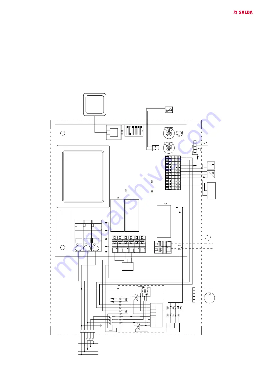
21.3.  VEKA INT E 700/9,0-L1 EKO

130.

78.

200.

0.

1-

L-

2k

PV

 - s

up

pl

y ai

r f

an E

C

,

IV

 - ex

trac

t ai

r f

an

 E

C

,

KE

1 -

 s

up

pl

y a

ir heat

er

,

AT

1 -

 aut

om

at

ic

 res

et

 ther

m

os

tat

 s

uppl

y ai

r

heat

er

,

R

T1 -

 m

anu

al

 res

et

 th

er

m

os

tat

 s

uppl

y ai

r

heat

er

,

TL -

 fr

es

ai

r t

em

per

at

ur

e s

ens

or

,

TJ

 - s

upp

ly

 ai

r t

em

per

at

ur

e s

ens

or

,

TE

 - 

ex

haus

t ai

r t

em

per

at

ur

e s

ens

or

,

M

2 -

 out

si

de ai

r dam

pe

r ac

tua

tor

,

M

5 -

 W

at

er

 c

ool

er

 v

al

ve ac

tua

tor

,

P/

U

 - "

Tr

ans

sm

iter

 1"

 s

uppl

y ai

r pr

es

sur

e

trans

m

itt

er

 (0-

10 V

D

C

),

P/

U

 - "

Tr

ans

sm

iter

 2"

 ex

tra

ct

 ai

r f

an 

0-

10V

pr

es

sur

e,

 C

O

2 t

rans

m

itt

er

s,

FA

 - f

ire

 al

ar

m

s i

npu

t,

R

G

1 -

 c

ont

rol

ler

 P

R

V-

...

 V

2.

2,

R

G

2 -

 c

ont

rol

ler

 E

SK

M

1-

26/

65Y

,

F2 -

 fus

e 2

50

m

A.

IV

+
L
N

PE

X15 
X14 
X5

X11 
X12

X14

E

C

O

20

0_107

ON

TJ

Su

ppl

y ai

r s

en

so

r

X7

T_

J

Y1

Y2

G

M5

24

V

AC

3

1

P

CO

O

LI

NG

F2

~

N

L Sup

L

VAL

+24V

VAL+

p-mA
GND

GND
Alarm

W

atte

r

C

O2

P

res

sur

e

R

ot

or

VAL-

p-10V

GND

0-10V

25

0m

A

N

230V

PE

N

By

E

CO

0-

10V

NO_F

Min Max

NO_F

X18

K1

X1

TR1

K2

LED2

RP1

X9

S1

K3

RP2

X15

X5

X2

LED5

LED4

X6

X12

X11

X13

LE

D7

LE

D6

LE

D3

PP

L

L

N

M2

X2

X6

R

em

ot

e c

ont

ro

l

N

F

PE

L3
L2
L1

K4

AT

1

A1

E

KR

-K

N3

 NI

S

V2

G

X3
X4

X9

X7

V1

A2

G

A1

X14
X17

X26

X12

A2

L2

L1

N

L3

PE

EA

S

EAS

PS
PS

PS

E

AS

R

T1

C

C

X1

4

PE

6

12

345

78

9

X3

3

X

29

W1

W2

W1

W

2

KE

Ex

tra

ct

 a

ir 

fa

n

(m

ax

. 1

0A

)

X

15

X1

3

X

32

0-

10

V

ou

t

G

ND

PV

L

N

PE

5

4

3

2

1

X3

5

4

3

2

1

6

X1

2

X1

1

X5

X15

X1

3

Sup

pl

ai

r f

an

(m

ax

. 10

A)

Содержание VEKA INT EKO Series

Страница 1: ...VEKA INT EKO SE MOUNTING AND INSTALLATION INSTRUCTION...

Страница 2: ...2 EKR K 17 19 4 LABELING CHARACTERISTICS OF THE CONTROLLER RG1 AND THE SYSTEM COMPONENTS 17 19 5 LABELING CHARACTERISTICS OF THE CONTROLLER RG2 18 19 6 FAULT INDICATION ON REMOTE CONTROL 18 19 7 MICRO...

Страница 3: ...voltage frequency Max current Max power consumption Protection class Weight xxx xx VAC Hz x xx A x xx kW IP xx xx kg Made in iauliai Lithuania AHU000000 BN xxxxxx 2019 01 01 SERIAL 2514523357 XXX GAMI...

Страница 4: ...e negative pressure in premises Great care should be taken when using at the same time in premises as another heating appliance what depend on the air in premises Such appliances include gas oil wood...

Страница 5: ...1 SW2 0 083 0 75 1 230 50 2 0 8 70 1 230 50 2 08 9 44 400 5 0 L1 SW2 0 083 0 75 1 230 50 5 0 12 5 2 400 50 5 08 13 32 700 2 4 L1 SW2 0 168 1 4 1 230 50 2 4 10 43 1 230 50 2 57 11 83 700 5 0 L1 SW2 0 1...

Страница 6: ...000 4000 construction 2 Supply fan 3 Exhaust fan 5 Electrical water heater pre heater 6 Control board 8 Supply air filter panel pocket 10 supply air damp er 7 DRIFTMILJ 5 C o 40 C o 40 C o 40 C o 15 C...

Страница 7: ...ove the film from the unit Remove the bracing packaging tape which keeps the protective profiles Remove the protective profiles After unpacking the unit examine it to make sure that it it has not been...

Страница 8: ...control box door H 400 mm 13 MONTAGE The protective film is intended to protect the unit during transportation It is recommended to remove the film because other wise oxidation signs may occur Before...

Страница 9: ...0 EKO Fig 13 3 VEKA INT 3000 4000 EKO 13 1 INSTALLATION UNDER THE CEILING Fig 13 1 1 under the ceiling installation NOTE For VEKA INT EKO with water heater install the air bleed system 14 CONNECTION O...

Страница 10: ...Supply air filter CO2 CO2 sensor M2 Outdoor air damper actuator M4 Water heater circular pump M5 Water cooler valve motor RC1 Stouch Flex or SA Control remote control panel M6 Water heater valve actu...

Страница 11: ...2 C2 E 700 5 0 L1 4x2 2 20 E 700 9 0 L1 5x2 5 3 20 E 700E 4 8 2x230 L2 3x4 2 B25 3x1 0 2 C2 E 1000 2 4 L1 3x2 1 16 E 1000 5 0 L1 4x2 5 2 20 E 1000 9 0 L1 5x2 5 3 20 E 1000 12 0 L1 5x3 3 25 E 1000E 7 2...

Страница 12: ...and or extract air filter s Filter replacement needed Filters are clogged and no message is shown on the remote control Wrong time in filter timers or their switch is broken or its pressure is set imp...

Страница 13: ...st lls automatiskt startar vid 50 C Det andra terst lls manuellt och startar p 100 C Om det manuella verhettningsskyddet l ser ut m ste aggregatet kopplas bort fr n n tsp nningen V nta tills v rmeelem...

Страница 14: ...INT EKO v2019 05 Fig 19 3 2 VEKA INT 1000 2000 EKO Fig 19 3 3 VEKA INT 3000 4000 EKO 19 4 VATTENBATTERI Vattenbatteriet kr ver inget ytterligare underh ll Byt luftfilter i tid i enlighet med det som s...

Страница 15: ...ghet st lls in via man verpanel Man verpanelen och aggregatet ansluts via kabel 4x0 2 mm Kabell ngd 13m Man verpanelen indikerar ven aggregatets driftl ge om det styrs via tryck CO2 ekonomil ge och la...

Страница 16: ...asser Erw rmungseinrichtung M4 ist eingeschaltet Leuchtet nicht Freonk hler bzw Zirkulationspumpe der Wasser Erw rmungseinrichtung M4 ist ausgeschaltet LED6 Leuchtet 3 Punkt Antrieb des Wasserventils...

Страница 17: ...TEN KENNZEIC NUNG BEZEICHNUNG DER KENNZEICHNUNG AUSGANG PARAMETER M1 Antrieb der Bypass Klappe K4 X17 N L By Speisung 230V AC Typ ON OFF M2 St lldon uteluftspj ll 230VAC K3 X17 N L Sup Speisung 230V A...

Страница 18: ...vierten Stufe X18 Maximale Belastung 6A Sicherungen des Kontrollers RG2 X27 X28 315mA 20 6 ST RUNGSANZEIGEN AM STEUERPULT NC Ingen kommunikation mellan man verpanel och aggregat Kontrollera kabel och...

Страница 19: ...ensor M2 outside air damper actuator M5 Water cooler valve actuator P U Transsmiter 1 supply air pressure transmitter 0 10 VDC P U Transsmiter 2 extract air fan 0 10V pressure CO2 transmitters FA fire...

Страница 20: ...anssmiter 1 supply air pressure transmitter 0 10 VDC P U Transsmiter 2 extract air fan 0 10V pressure CO2 transmitters FA fire alarms input RG1 controller PRV V2 2 RG2 controller ESKM1 26 65Y F2 fuse...

Страница 21: ...nput RG1 controller PRV V2 2 RG2 controller ESKM1 26 65Y F2 fuse 250mA IV L N PE X15 X14 X5 X11 X12 X14 ECO200_107 ON TJ Supply air sensor X7 T_J Y1 Y2 G M5 24VAC 3 1 P COOLING F2 N L Sup L VAL 24V VA...

Страница 22: ...22 SE VEKA INT EKO v2019 05 21 4 VEKA INT E 1000 5 0 L1 EKO...

Страница 23: ...SE 23 VEKA INT EKO v2019 05 21 5 VEKA INT E 1000 9 0 L1 EKO VEKA INT E 1000 12 0 L1 EKO...

Страница 24: ...24 SE VEKA INT EKO v2019 05 21 6 VEKA INT E 2000 6 0 L1 EKO...

Страница 25: ...N L VAL VAL VAL 24V p 10V GND p mA GND Alarm GND 0 10V NO_F NO_F X13 X14 X15 X17 X19 X20 X7 X8 X9 X18 L By Sup L N N EAS EAS EAS X16 2 X16 2 X23 8 1 2 3 4 5 9 2 1 N L L contr 0 10V ECO Rotor Pressure...

Страница 26: ...26 SE VEKA INT EKO v2019 05 21 8 VEKA INT E 2000 21 0 L1 EKO...

Страница 27: ...SE 27 VEKA INT EKO v2019 05 21 9 VEKA INT 1000 W EKO...

Страница 28: ...28 SE VEKA INT EKO v2019 05 21 10 VEKA INT 2000W EKO...

Страница 29: ...SE 29 VEKA INT EKO v2019 05 21 11 VEKA INT EKO 3000 15KW L1...

Страница 30: ...30 SE VEKA INT EKO v2019 05 21 12 VEKA INT EKO 3000 21KW L1...

Страница 31: ...SE 31 VEKA INT EKO v2019 05 21 13 VEKA INT EKO 3000 30KW L1...

Страница 32: ...32 SE VEKA INT EKO v2019 05 21 14 VEKA INT EKO 3000 39KW L1...

Страница 33: ...SE 33 VEKA INT EKO v2019 05 21 15 VEKA INT EKO 4000 21KW L1...

Страница 34: ...34 SE VEKA INT EKO v2019 05 21 16 VEKA INT EKO 4000 27KW L1...

Страница 35: ...SE 35 VEKA INT EKO v2019 05 21 17 VEKA INT EKO 4000 39KW L1...

Страница 36: ...36 SE VEKA INT EKO v2019 05 21 18 VEKA INT EKO 4000 54KW L1...

Страница 37: ...d Tryckstyrd Tryckstyrd ljudeffektniv f r bost der Lwa dB A 49 49 49 57 57 57 ErP Compliance 2018 2018 2018 2018 2018 2018 Webbadress f r anvisningar f r is rtagning www salda lt VEKA INT EKO 1000 2 4...

Страница 38: ...dubbelriktad dubbelriktad Typ av drivenhet som r installerad stegl s varvtalsreg ulator stegl s varvtalsreg ulator stegl s varvtalsreg ulator stegl s varvtalsreg ulator stegl s varvtalsreg ulator Typ...

Страница 39: ...125 125 Statisk verkningsgrad f r fl ktar som an v nds i enlighet med f rordning EU nr 327 2011 56 4 56 4 56 4 56 4 56 4 Deklarerad maximal yttre l ckfaktor f r ven tilationsenheters h lje 1 1 1 1 1...

Страница 40: ...duction LST EN 60204 1 2006 Safety of machinery Electrical equipment of machines Part 1 General requirements LST EN 60335 1 2012 Household and similar electrical appliances Safety Part 1 General requi...

Страница 41: ...he equipment to manufacturer Delivery costs should be covered by customer Manufacturer reserves the right to change this technical passport any time without prior notice if some typographic errors or...

Страница 42: ...42 VEKA INT EKO v2019 05...

Страница 43: ...43 VEKA INT EKO v2019 05...

Страница 44: ...lt UNDERH LLSSCHEMA Produktnamn LOT nummer Installation Intervall Datum Reng rning av fl kt En g ng per r Reng rning av v xlare En g ng per r Filter Varje 3 4 m nad Se aggregatets etikett Minst OBS K...

Отзывы: