37
Smarty 3X VE / Smarty 3X VE 3.0
www.salda.lt
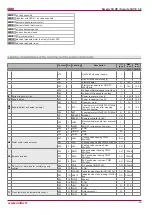
Name
ModBus func.
Data
address
Quantity
of
data
Description
Values
1
Antifrost
01h_Read_Coils
0
1
Plate heat exchanger frost protection function
1-active,
o-passive
2
Fire
01h_Read_Coils
1
1
Fire alarm
1-active,
o-passive
3
Filter
01h_Read_Coils
2
1
Dirty filter alarm
1-active,
o-passive
4
Fan
01h_Read_Coils
3
1
Fans alarm
1-active,
o-passive
5
LowPower
01h_Read_Coils
5
1
Low voltage
1-active,
o-passive
6
Textract
01h_Read_Coils
6
1
DTJ(100) temperature sensor alarm
1-active,
o-passive
7
Texhaust
01h_Read_Coils
7
1
Exhaust air temperature sensor alarm
1-active,
o-passive
8
Tlimit
01h_Read_Coils
8
1
Supply air temperature sensor alarm
1-active,
o-passive
9
RH
01h_Read_Coils
9
1
DTJ(100) humidity sensor alarm (controller works in deter-
mining themoisture content of 70%)
1-active,
o-passive
10 ToutDoor
01h_Read_Coils
11
1
Outside air temperature sensor alarm (controller continues
to work in determining ToutDoor<0C)
1-active,
o-passive
11
MotorAc-
tive
01h_Read_Coils
13
1
Fans ON
1-active,
o-passive
12 InDumpper 04h_Read_Input
14
1
Outside air damper actuator
0-90
13 Preheater
01h_Read_Coils
12
1
Preheater indication
1-active,
o-passive
14 Heater
01h_Read_Coils
14
1
Heater indication
1-active,
o-passive
15 Speed
06h_Write_Hold-
ing_Register
0
1
Fans speed settings
0, 1, 2, 3
16 TsetPoint
06h_Write_Hold-
ing_Register
1
1
Supply air temperature set
0-30
17 RH_value
04h_Read_Input
13
1
DTJ(100) humidity sensor value
0-99
18 Motor1
04h_Read_Input
15
1
Motor1 fan speed value
0-3
19 Motor2
04h_Read_Input
16
1
Motor2 fan speed value
0-3
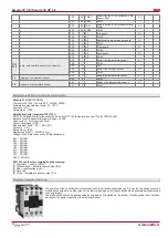
Temperature sensor value real format (-3.3E38 - 3.3E38) example: 0h->0C, 7FFFh->3276.7C, 8000h->3276.8, FFFFh->-0.1C
20 Tlimit
04h_Read_Input
0
1
Supply air temperature value
Real
(
value*10
)
21 Texhaust
04h_Read_Input
6
1
DTJ(100) temperature sensor value
Real
(
value*10
)
22 Textract
04h_Read_Input
3
1
Exhaust air temperature sensor value
Real
(
value*10
)
23 ToutDoor
04h_Read_Input
9
1
Ouside air temperature sensor value
Real
(
value*10
)
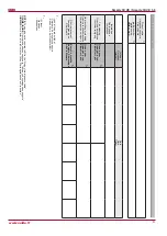
Failure
Cause
Explanation / corrective actions
Unit is not operating
No supply voltages
Check if the plug is connected to the plug
socket
Two-pole protection device is off or a cur-
rent leakage relay is active (if installed by the
installer)
Switch on only if the unit condition has been
evaluated by a qualified electrician. If the sys-
tem failed, the failure MUST BE rectified prior
to switching it on.
Unit door is not properly closed
Visually inspect whether the door properly
presses the end switch
Air supply heater or preheater is not operating
or malfunctioning (if installed)
Too low air flow in air ducts activates automatic
protection
Check if air filters are not clogged
Check if fans are rotating
Manual protection is activated
Possible heater or unit failure. MUST address
the servicing staff for failure detection and its
elimination.
Too low air flow at rated fan speed
Clogged supply and/or extract air filter(s)
Filter replacement needed


