EN |
17
RIRS 1200-5500 H EKO 3.0 v2019.06
1.790.0047A.0.1.2-L-0k
CE7/7
X16.7
PE N L1
L1
N
PE
L1
N
PE
L1
N
PE
1f, 230V AC
Power
supply cable
X16
36
36
28
25
20
22 23 24
24
23
22
23 24
X16.4
25
25
31
30
X16.7 29
34
33
32
35 36
30
29
31
33
32
34 35
27
26
28
30
29
31
33
32
34 35
27
26
28
26 27
X16.10
15
18
17
X16.5
19
17
15
14
13
12
11
22
21
11 12 13 14 15
17 18 19 20 21
21
20
19
18
12
11
X16.4
9 10
6
5
4
X16.3
7 8
14
13
X16.2
1 2 3 4 5 6 7 8 9 10
10
9
8
7
6
5
4
3
2
1
X16.1
2 3
1
16
16
16
M2
N
L
230V AC
Air quality transmitter
P
Transmitter 1
23 - 24V DC,
24 - intput, 0-10V DC,
25 - GND,
1f, 230V AC
PE
M4
L
N
circulation pump
Water heater
Water heater
valve actuator
Water heater
antifrost protect.
0 - GND,
Y - 0-10V,
G - 24VDC.
0
Y
G
M6
24VDC, 0-10VDC
X16.8
41
TV
T1
X16.9
P
26 - 24V DC,
27 - intput, 0-10V DC,
28 - GND,
Transmitter 2
CO2; Supply air pressure
Air quality transmitter
Extract air pressure
Fire alarm
input
damper actuator
damper actuator
Extract air
Supply air
L
L c
ont
rol
N
L c
ont
rol
ON/OFF
ON/OFF
230V AC
L
L
N
M3
N
X16.6
temp.sensor
TJ
Supply air
NTC
A
H
U
wo
rk
1.
2W
m
ax
1.
2W
m
ax
A
H
U
st
op
X16.4
DX Cooling
P
1
3
24
V
DC
24
V
DC
AHU stop
AHU work
AHU status
Start/Stop
Boost
Y1 - OPEN (24VAC)
Y2 - CLOSE (24VAC)
G - System potential 24VAC
24VAC, 3-position
M5
G
Y2
Y1
Water cooler
valve actuator
Jumper
ST
O
P-
N
O
ST
AR
T-
N
C
BO
O
ST
CE7/7
X16.7
PE N L1
L1
N
PE
L1
N
PE
L1
N
PE
1f, 230V AC
Power
supply cable
X16
36
36
28
25
20
22 23 24
24
23
22
23 24
X16.4
25
25
31
30
X16.7 29
34
33
32
35 36
30
29
31
33
32
34 35
27
26
28
30
29
31
33
32
34 35
27
26
28
26 27
X16.10
15
18
17
X16.5
19
17
15
14
13
12
11
22
21
11 12 13 14 15
17 18 19 20 21
21
20
19
18
12
11
X16.4
9 10
6
5
4
X16.3
7 8
14
13
X16.2
1 2 3 4 5 6 7 8 9 10
10
9
8
7
6
5
4
3
2
1
X16.1
2 3
1
16
16
16
M2
N
L
230V AC
Air quality transmitter
P
Transmitter 1
23 - 24V DC,
24 - intput, 0-10V DC,
25 - GND,
1f, 230V AC
PE
M4
L
N
circulation pump
Water heater
Water heater
valve actuator
Water heater
antifrost protect.
0 - GND,
Y - 0-10V,
G - 24VDC.
0
Y
G
M6
24VDC, 0-10VDC
X16.8
41
TV
T1
X16.9
P
26 - 24V DC,
27 - intput, 0-10V DC,
28 - GND,
Transmitter 2
CO2; Supply air pressure
Air quality transmitter
Extract air pressure
Fire alarm
input
damper actuator
damper actuator
Extract air
Supply air
L
L c
on
trol
N
L c
ont
rol
ON/OFF
ON/OFF
230V AC
L
L
N
M3
N
X16.6
temp.sensor
TJ
Supply air
NTC
A
H
U
wo
rk
1.
2W
m
ax
1.
2W
m
ax
A
H
U
st
op
X16.4
DX Cooling
P
1
3
24
V
DC
24
V
DC
AHU stop
AHU work
AHU status
Start/Stop
Boost
Y1 - OPEN (24VAC)
Y2 - CLOSE (24VAC)
G - System potential 24VAC
24VAC, 3-position
M5
G
Y2
Y1
Water cooler
valve actuator
Jumper
ST
O
P-
N
O
ST
AR
T-
N
C
BO
O
ST
1.790.0047A.0.1.2-L-0k
1.790.0047A.0.1.2-L-0k
FA
NC
Jumper
FA
NC
Jumper
FA
NC
Jumper
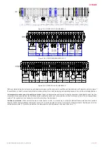
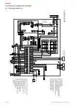
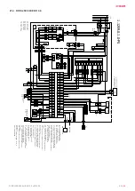
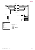
Figure 19.5.2. RIRS 1200-1900 HW EKO 3.0
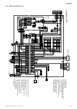
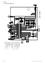
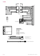
Figure 19.5.3. RIRS 2500-5500 HE EKO 3.0
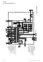
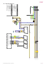
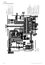
Figure 19.5.4. RIRS 2500-5500 HW EKO 3.0
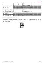
Before commissioning, device launching and adjustment works must be done only by qualified and trained personnel. Automatic control system of
the ventilation unit must be properly adjusted to work adequately. Also, install measuring and operating devices in line with the provided guidelines.
Air temperature sensors and air quality converters.
Supply air temperature sensors and air quality converters (if additionally used) must be
mounted as far as possible from the ventilation devices (within the confines of sensor cable) up to the first branch or turn of the air transportation
system. This requirement is necessary to ensure the accuracy of measurement.
Antifreeze protection.
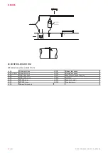
When external supply air water heater is used, it is necessary to properly install antifreeze protection from possible
freezing of heat carrier. Antifreeze temperature sensor (TV) must be mounted in clamp on return pipe of the water heater. Capillary sensor of the
antifreeze thermostat (T1) must be mounted on the water heater and its adjustment knob must be set at +5 °C.
Содержание RIRS EKO 3.0 1200 HE
Страница 1: ...RIRS 1200 5500 H EKO 3 0 EN MOUNTING AND INSTALLATION INSTRUCTION ...
Страница 28: ...28 EN RIRS 1200 5500 H EKO 3 0 v2019 06 21 7 RIRS 3500 HW EKO 3 0 ...
Страница 37: ... 37 RIRS 1200 5500 H EKO 3 0 v2019 06 ...
Страница 38: ...38 RIRS 1200 5500 H EKO 3 0 v2019 06 ...
Страница 39: ... 39 RIRS 1200 5500 H EKO 3 0 v2019 06 ...


