Page 5
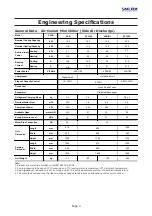
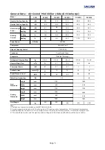
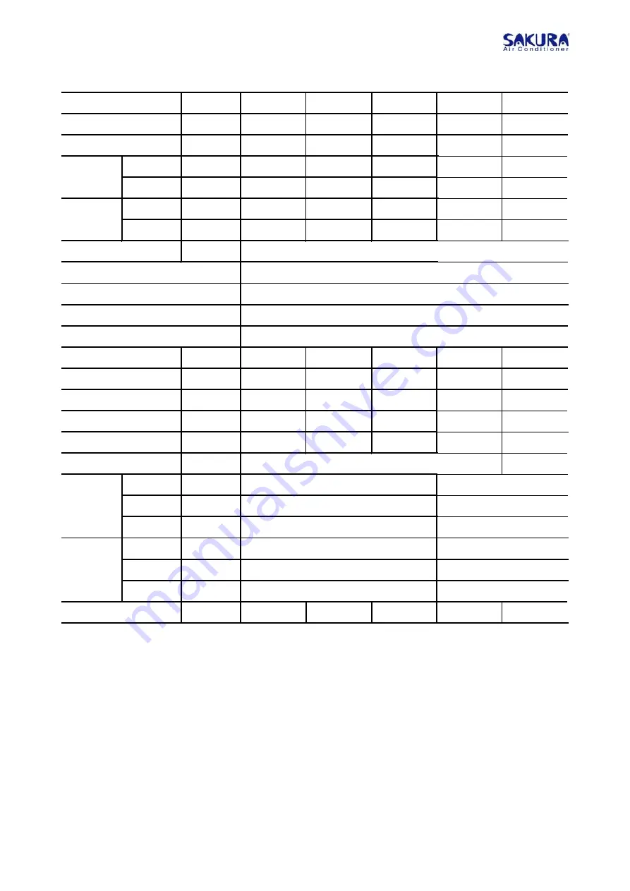
General Data - Air-Cooled Mini Chiller (Side Air Discharge)
Note:
1. Product are tested in accordance to GB/T18430.2-2008
2. Cooling capacity is based on 12°C entering and 7°C leaving water temperature, 35°C ambient temperature.
3. Heating capacity is based on 40°C entering and 45°C leaving water temperature, 7°C ambient temperature.
4. The manufacturer reserves the rights to make changes to the abov
HVSHFL¿FDWLRQVZLWKRXWSULRUQRWLFH
FVCA
120 B(R)
150 B(R)
200 B(R)
kW
31.5 40.0 50.0
kW
34.0
43.0
54.0
Cooling
kW
10.4
13.0
18.1
Heating
kW
11.0
13.5
18.5
Cooling
A
20.2
27.5
32.2
Heating
A
22.2`
27.6 32.5
V/Ph/Hz
kg
4.0 x 2
5.0 x 2
5.4 x 2
m
3
/h
5.4
6.9
8.6
kW
0.7
1
1
meter H
2
O
15
18
18
dBA
65
69
69
DN
40
Length
mm
Width
mm
Height
mm
Length
mm
Width
mm
Height
mm
kg
390
470
550
Model
Nominal Input
Power
Running
Current
Power Source
Nominal Cooling Capacity
Nominal Heating Capacity
Available Head
Water Pipe Connection
Unit Weight
Unit
Dimension
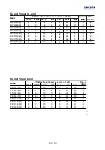
Sound Pressure Level
Packing
Dimension
32
Refrigerant Charging Mass
Nominal Water Flow
Pump Input Power
Evaporator
Compressor
Condenser
Stage of Capacity Control
380/3/50
Hermetic Scroll
0-50%-100%
Cross Finned Tubes
Plate Heat Exchanger
1180
1880
480
480
1755
1755
1300
2000
680
680
1940
1940
80 B(R)
100 B(R)
20.0
27.0
23.0
30.0
6.7
8.8
7.2
9.2
13.9
18.0
14.1 18.2
3.0 x 2
3.5 x 2
3.4
4.7
0.7
0.7
20
16
63
65
350
350
Содержание FVCA-40 B
Страница 27: ...Page 2 Dimensions Dimension in mm Model FVCA 50C R 60B R Model FVCA 40B Dimension in mm...
Страница 28: ...Page 2 Model FVCA 150 200 B R Dimension in mm Dimension in mm Model FVCA 80 C R 80 100 120 B R...
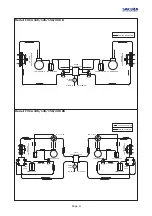
Страница 29: ...Page 2 Wiring Diagram Wiring Diagrams Model FVCA 40B...
Страница 30: ...Page 2 Wiring Diagram Model FVCA 50C Model FVCA 50CR...
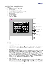
Страница 31: ...Page Model FVCA 60B Model FVCA 60BR...
Страница 32: ...Page Model FVCA 80 C Model FVCA 80 CR...
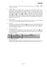
Страница 33: ...Page 3 Model FVCA 80 100 120 B Model FVCA 80 100 120 BR...
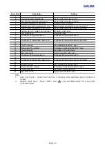
Страница 34: ...Page 3 Model FVCA 150 200 B Model FVCA 150 200 BR...


