SAINT-GOBAIN NORTON Clipper CWM 216 Скачать руководство пользователя страница 19

VERS. 04.12.2019 

 MAN CWM 216/254 EN 


19 

TRANSPORT AND STORING 


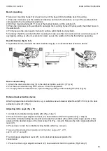
2.1  Securing for transport 

 
Before transporting the machine, please follow the following instructions: 


Switch the product off and disconnect it from the power supply. 


Slide the cutting head fully forwards and tighten the slide locking knob (8) to avoid accidental sliding 
movement of the upper part. 


Follow the reverse order of “Assembly – Operation position” to set the product at locking position. 


Always carry the product by its base and transport handle. Never use the cord for carrying the product. 


Protect the product from any heavy impact or strong vibrations which may occur during transportation 
in vehicles. 


Secure the product to prevent it from slipping or falling over. 


2.2  Storing of the machine 


Switch the product off and disconnect it from the power supply. 


Clean the product with a dry cloth. Use a brush for areas that are hard to reach. 


In particular, clean the switches and air vents after every use with a cloth and brush. 


Remove stubborn dirt with high pressure air (max. 3 bar). 


Check for worn or damaged parts. Replace worn parts as necessary or contact an authorised service 
centre for repair before using the product again. 


Slide the cutting head fully forwards and tighten the slide locking knob (8) if necessary. 


Follow the reserve order of “Assembly – Operation position” to set the product at locking position. 


Store the product and its accessories in a dark, dry, frost-free, well-ventilated place. 


Always store the product in a place that is inaccessible to children. The ideal storage temperature is 
between 10°C and 30°C. 


We recommend using the original package for storage or covering the product with a suitable cloth or 
enclosure to protect it against dust. 


Содержание NORTON Clipper CWM 216

Страница 1: ...CWM 216 254 OPERATING INSTRUCTIONS Translation of the original instructions...

Страница 2: ...VERS 04 12 2019 MAN CWM 216 254 EN 2...

Страница 3: ...6 95 CE LECTROMAGN TIC COMPATIBILITY 2004 108 CE NOISE 2000 14 CE and European standard EN 61029 1 2009 A11 2010 EN 61029 2 9 2012 A11 2013 Valid for machines as of serial number 4502790460 Storage si...

Страница 4: ...VERS 04 12 2019 MAN CWM 216 254 EN 4...

Страница 5: ...ut 9 1 6 Technical data 18 1 7 Statement regarding noise emission 18 1 8 Electrical connections 18 1 9 Starting the machine 18 2 TRANSPORT AND STORING 19 2 1 Securing for transport 19 2 2 Storing of t...

Страница 6: ...oards as well as for furniture construction parts in non ferrous materials Symbols Important warnings and pieces of advice are indicated on the machine using symbols The following symbols are used on...

Страница 7: ...1 Machine plate Important data can be found on the following plate located on the machine Machine Model Machine Code Maximum blade diameter and bore size Serial number Power Electrical Insulation Clas...

Страница 8: ...nning Do not move the machine whilst the blade is idling Always cut with the blade guard in position SAFETY INSTRUCTIONS FOR LASER a Do not stare directly at the laser beam A hazard may exist if you d...

Страница 9: ...construction or industrial site Combined with NORTON Wood or aluminium blades it offers high performance and quality cuts of materials used in construction The machine and its component parts are asse...

Страница 10: ...VERS 04 12 2019 MAN CWM 216 254 EN 10...

Страница 11: ...assembled Insert the height adjustment pillar 11b into the work piece clamp holder 38 on either side of the base if necessary Fence fig C Install 1 Unlock the fence locking lever 37 step 1 2 Align th...

Страница 12: ...amping screw 34a slightly with the provided multi tool until the spindle is locked 5 Loosen the clamping screw 34a clockwise and remove it together with the washer the spindle 34d Fig F 6 Place a new...

Страница 13: ...1 Attach the dust collection bag 5 to the dust extraction outlet 41 Fig G 2 Pull the dust collection bag off to remove it from the appliance 3 To empty the dust collection box open the bag by pulling...

Страница 14: ...ngle on the bevel scale 10 Fig L step 3 Always ensure the saw blade does not interfere with the fence or any other parts Remove the fence if necessary 4 Lock the bevel angle locking lever Fig L step 4...

Страница 15: ...p 1 to allow the cutting head to slide freely step 2 Adjusting extension supporter fig O Use the extension supporter for supporting long work pieces Use an additional support for extremely long work p...

Страница 16: ...height of the bracket 11d and plate 11c Ensure the motor housing does not interfere with the clamp while operation with the cutting head set to the required bevel and miter angle 1 Loosen the locking...

Страница 17: ...aser symbol of the laser switch 3 4 Switch the laser off by pressing the OFF of the laser switch The laser line should be aligned with the blade cutting path Readjustment of the laser shall always be...

Страница 18: ...and ear protection measures are necessary 1 8 Electrical connections Check that The voltage phase supply corresponds to the information indicated on the machine Available power supply must have ground...

Страница 19: ...itch the product off and disconnect it from the power supply Clean the product with a dry cloth Use a brush for areas that are hard to reach In particular clean the switches and air vents after every...

Страница 20: ...a so you can work safely Set the machine on the flat and stable ground 3 1 2 Space required for operation and maintenance In order to use and maintain the machine safely and correctly leave 2 m in fro...

Страница 21: ...er source e g generator has too low Voltage 2 3 Air vents are blocked 2 1 Use a proper extension cord 2 2 Connect to another power Source 2 3 Clean the air vents 3 Product does not cut 3 1 Not connect...

Страница 22: ...appropriate to us but which is not always the quickest way Clear instructions will avoid problems and faulty deliveries If not sure please send us the defective part In the case of a warranty claim th...

Страница 23: ...ck access you can also use the QR Code shown below using your mobile phone This electronic catalogue provides exploded views and spare parts lists for different machines designed by Norton Clipper so...

Страница 24: ...OROCCO TEL 212 5 22 66 57 31 FAX 212 5 22 35 09 65 SAINT GOBAIN ABRASIVES BV GROENLOSEWEG 28 7151 HW EIBERGEN P O BOX 10 7150 AA EIBERGEN THE NETHERLANDS TEL 31 545 466466 FAX 31 545 474605 SAINT GOBA...

Отзывы: