


Saia-Burgess Controls AG
Manual PCD7.D412DTPF & PCD7.D4xxxT5F │ Document 27-620 – Release ENG07 │ 2019-06-20
5-3
Structure and description of the Setup menu
Logic Controller (pWeb panels, only)
5
5.2
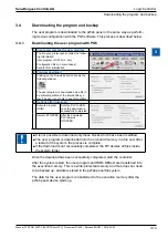
Logic Controller (pWeb panels, only)
Settings of the programmable logic controller in pWeb panels. The settings config
-
ured here can also be made in the PG5 Device configurator.
If the Device Configuration is updated via PG5, the data set in Setup is overwritten. If you want this
data to be carried over to the PG5, the configuration requires the configuration file to be uploaded
into the PG5 project.
5.2.1
Program Name
Displays the name of the loaded PG5 project.
5.2.2
Status: RUN or HALT
Displays the status of the logic controller.
5.2.3 S-BUS
Configuration of the S-bus of the internal logic controller.
Î
S-Bus Station
S-bus station of the logic controller
Î
Serial
Settings for the serial S-bus connection
●
Active
Activates the serial connection
●
PGU
When PGU is activated, the panel can be programmed via the serial inter
-
face
●
Port
For setting the S-bus port
●
Mode
Data or parity
●
Baud reate
Speed of the S-bus
●
TS Delay
Sets a transmission delay. Setting 0 causes the default values to be used
●
TN Delay
Sets a transmission delay. Setting 0 causes the default values to be used